AFMS, GARMIN G500 PFD/MFD SYSTEM 190-01102-01 Rev. 9
FAA APPROVED Page 10 of 40
Equipment that receives power from two different circuit breakers will be
suffixed with the letters A and B. For example: PFD 1A and PFD 1B, or PFD
2A and PFD 2B.
1.3 Navigation Sources
The G500 requires at least one Garmin GPS/SBAS navigation unit to ensure the
integrity of the Attitude and Heading Reference System. The AHRS will still
operate in a reversionary mode if the GPS fails, and the PFD attitude display
will still be presented, see Paragraph 2.8. The G500 HSI can be selected to
display course deviation information from up to four independent sources: two
GPS, and two VHF NAV. In addition, the HSI can display two simultaneous
bearing pointers sourced from GPS, VHF NAV, or ADF.
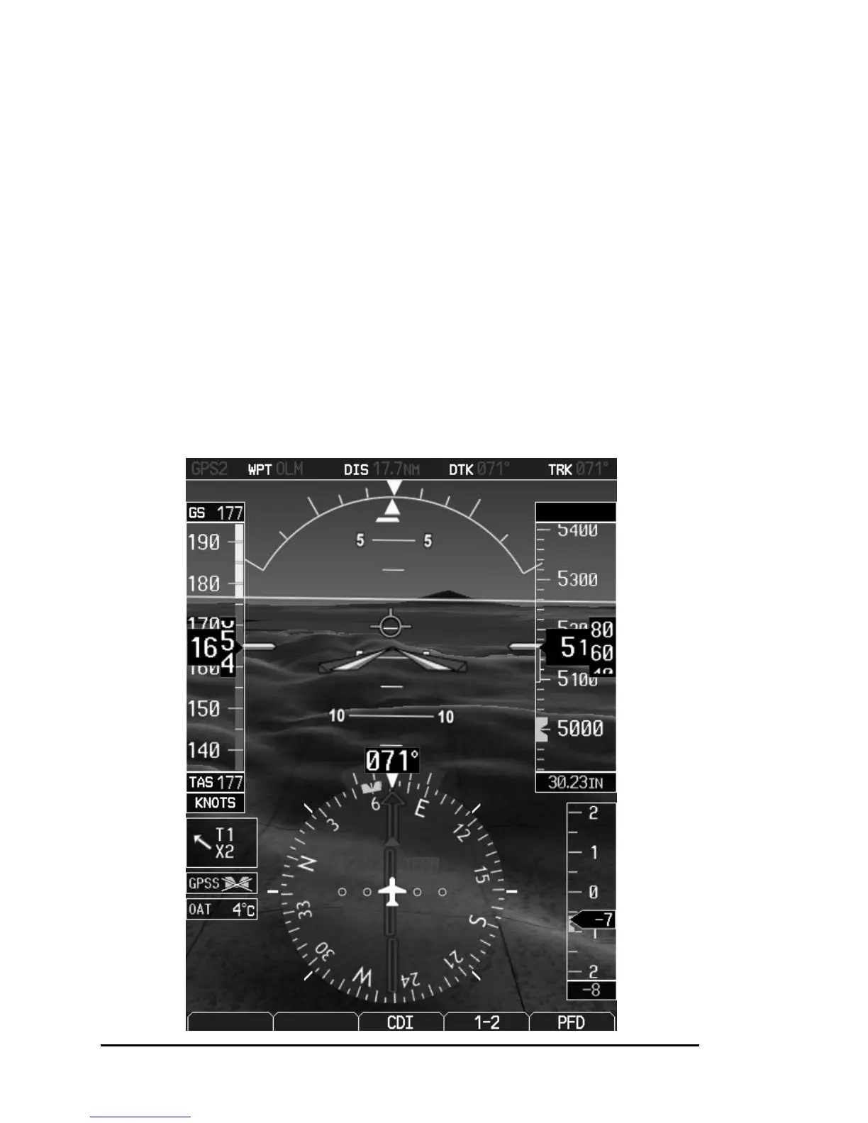
1.4 Synthetic Vision Technology
SVT uses an internal terrain database and GPS location to present the pilot with
a synthetic view of the terrain in front of the aircraft. The purpose of the SVT
system is to assist the pilot in maintaining situational awareness with regard to
the terrain and traffic surrounding the aircraft. A typical SVT display is shown
below:

 Loading...