AFMS, GARMIN G500 PFD/MFD SYSTEM 190-01102-01 Rev. 9
FAA APPROVED Page 13 of 40
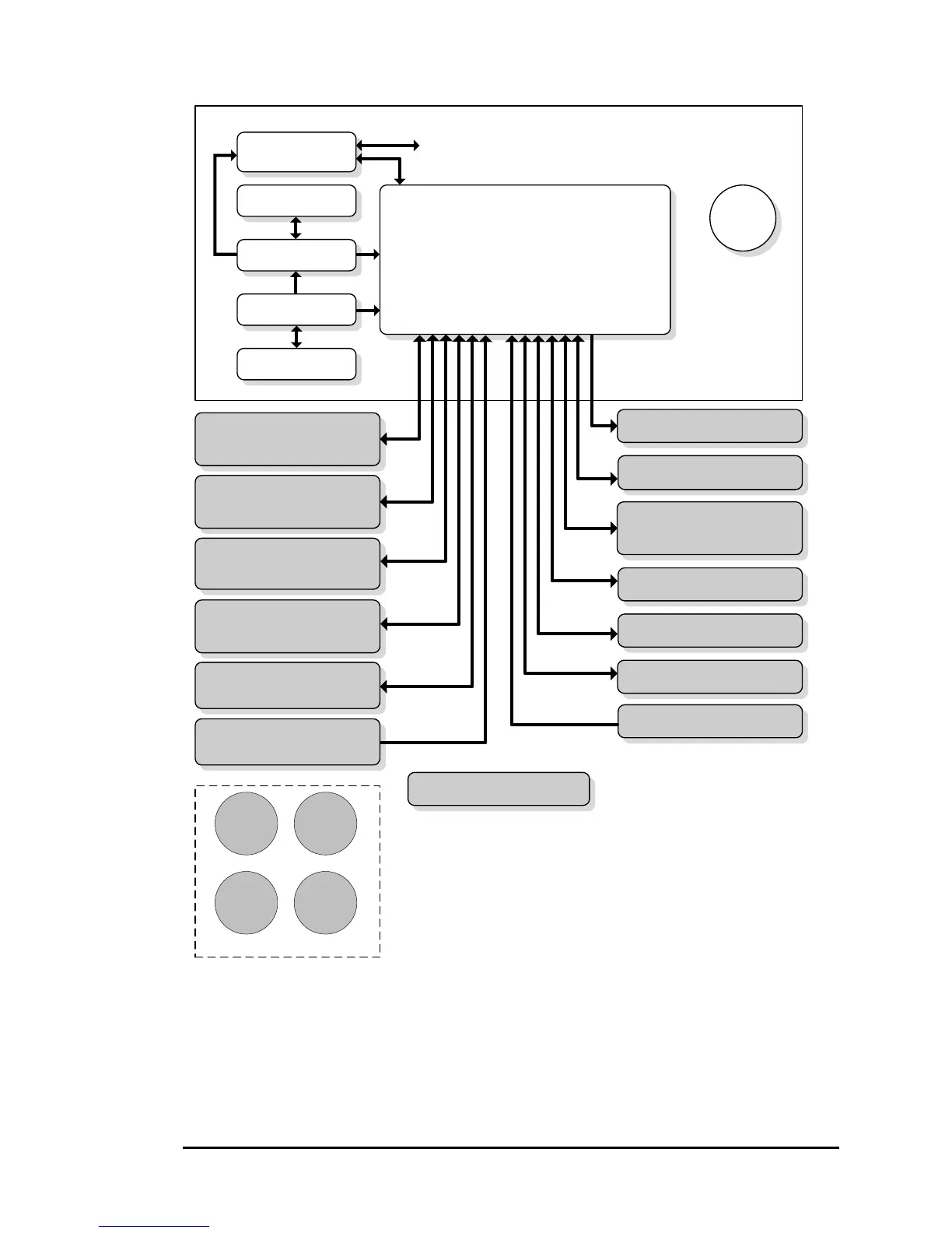
1.11 Single G500 Operational Block Diagram
Standby
Attitude*
Standby
Airspeed
Standby
Altimeter
Magnetic
Compass
Equipment Installed per this STC
(required)
PFD/MFD Display
GDU 620
*Standby Attitude: may be replaced
with electric attitude indicator with
integral / dedicated backup battery.
**Audio panel connection to GDU 620
is recommended for tones and aural
alerts generated by the GDU 620.
This MUST be connected if SVT is
enabled.
*** Installation of a Mid-Continent
electric standby attitude indicator is
approved by this STC.
Air Data Computer
AHRS
Magnetometer
GMU 44
GRS 77
GDC 74()
Temperature Probe
GTP 59
No. 1 GPS/SBAS Navigator
(required)
No. 1 VOR/Localizer/GS
(optional)
No. 2 GPS/SBAS Navigator
(optional)
No. 2 VOR/Localizer/GS
(optional)
Autopilot/Flight Director
(optional)
ADF
(optional)
Audio Panel
(optional)
**
Traffic
(optional)
XM WX/Entertainment
GDL 69/69A
(optional)
Adapter
(optional)
GAD 43/43e
to Aircraft Systems
Weather Radar
(optional)
Electric
Standby
Attitude***
(optional)
Radar Altimeter
(optional)
Iridium Data Link
(optional)
Existing Equipment
(already installed in aircraft)
Video Source
(optional)

 Loading...