Θi+1 = (Irms /k*IFLA) ² · [1 – exp (-t/Te)] + Θi · exp (-t/Te)
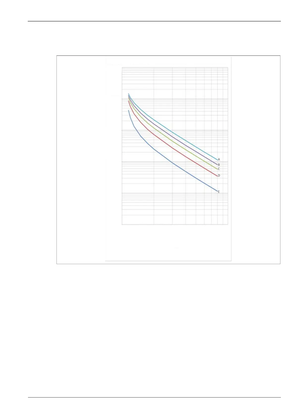
TRIPPING CURVE FUNCTION OF THE PREFAULT LOAD (K = 1.1 & Te = 10 Mins)
TIME IN SEC
10000.00
1000.00
100.00
10.00
1.00
0.10
1 10
MULTIPLES OF THERMAL THRESHOLD SETTINGS Iθ>
A: No. of prefault load, thermal state = 0%
B: Thermal state = 30%
C: Thermal state = 50%
D: Thermal state = 70%
E: Thermal state = 90%
P5005ENa
Figure 5: Thermal Overload curve
2.5.1 Thermal Overload Protection Implementation
The device incorporates a current-based thermal characteristic, using fundamental load current to
model heating and cooling of the protected plant. The element can be set with both alarm and trip
stages.
Thermal Overload protection is implemented in the THERMAL OVERLOAD column of the relevant
settings group. The magnitudes of the three phase input currents are compared and the largest
magnitude is taken as the input to the thermal overload function.
Thermal over load function supports setting for alarm and trip stages. If the thermal overload function
is enabled and thermal state of the protected equipment exceeds the alarm threshold setting, the
alarm is issued and indicated by illuminated START LED on the relay front panel.
If the thermal overload function is enabled and thermal state of the protected equipment exceeds the
Trip threshold setting, a trip command is issued resulting in operation of output contacts. Trip condition
is indicated by illuminated TRIP LED.
 Loading...


