Caution: All screws of fitting clamps to be properly tightened. Always
use M4 x 12 screws for fitting the clamps.
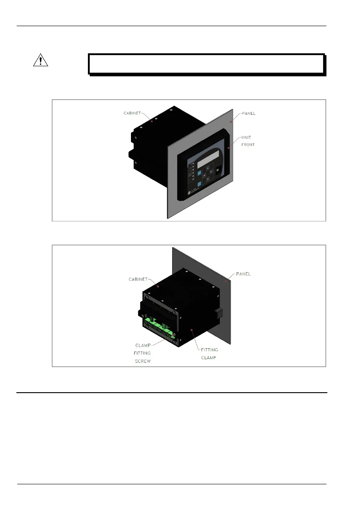
3. The mounted relay is shown below.
Figure 3: Relay mounted on the panel-front view
Figure 4: Relay mounted on the panel-rear view
2.3 Relay Connection
Before installation of the relay check the correct working procedure as to ensure safety. The terminal
exposed during installation may present a hazardous voltage unless the equipment is electrically
isolated. Any disassembly of the equipment may expose parts to hazardous voltage. Electronic parts
may be damaged if suitable electrostatic discharge (ESD) precautions are not taken. Voltage and
current connection should be made using insulated crimp termination to ensure that terminal block
insulation requirements are maintained for safety. To ensure that wires are correctly terminated the
correct crimp terminal and tool for wire size should be used. The equipment must be connected in
accordance with the appropriate connection diagram.
 Loading...


