2 SCADA COMMUNICATIONS
2.1 Modbus
This section describes how the MODBUS standard is applied to the Px50 platform. It is not a
description of the standard itself. The level at which this section is written assumes that the reader is
already familiar with the MODBUS standard.
The MODBUS protocol is a master/slave protocol, defined and administered by the MODBUS
Organization. For further information on MODBUS and the protocol specifications please see the
Modbus web site (www.modbus.org).
2.1.1 Overview
2.1.1.1 Physical Connection and Link Layer
Only one option is available for connecting MODBUS.
• Rear serial port 1 - for permanent SCADA connection via EIA(RS)485
The MODBUS interface uses ‘RTU’ mode communication rather than ‘ASCII’ mode as this provides
more efficient use of the communication bandwidth. This mode of communication is defined by the
MODBUS standard.
The IED address and baud rate can be selected using the front panel menu or with P50 Agile
configurator.
When using a serial interface, the data format is: 1 start bit, 8 data bits, 1 stop bit (a total of 10 bits per
character).
2.1.2 MODBUS Functions
2.1.2.1 Protocol Mapping
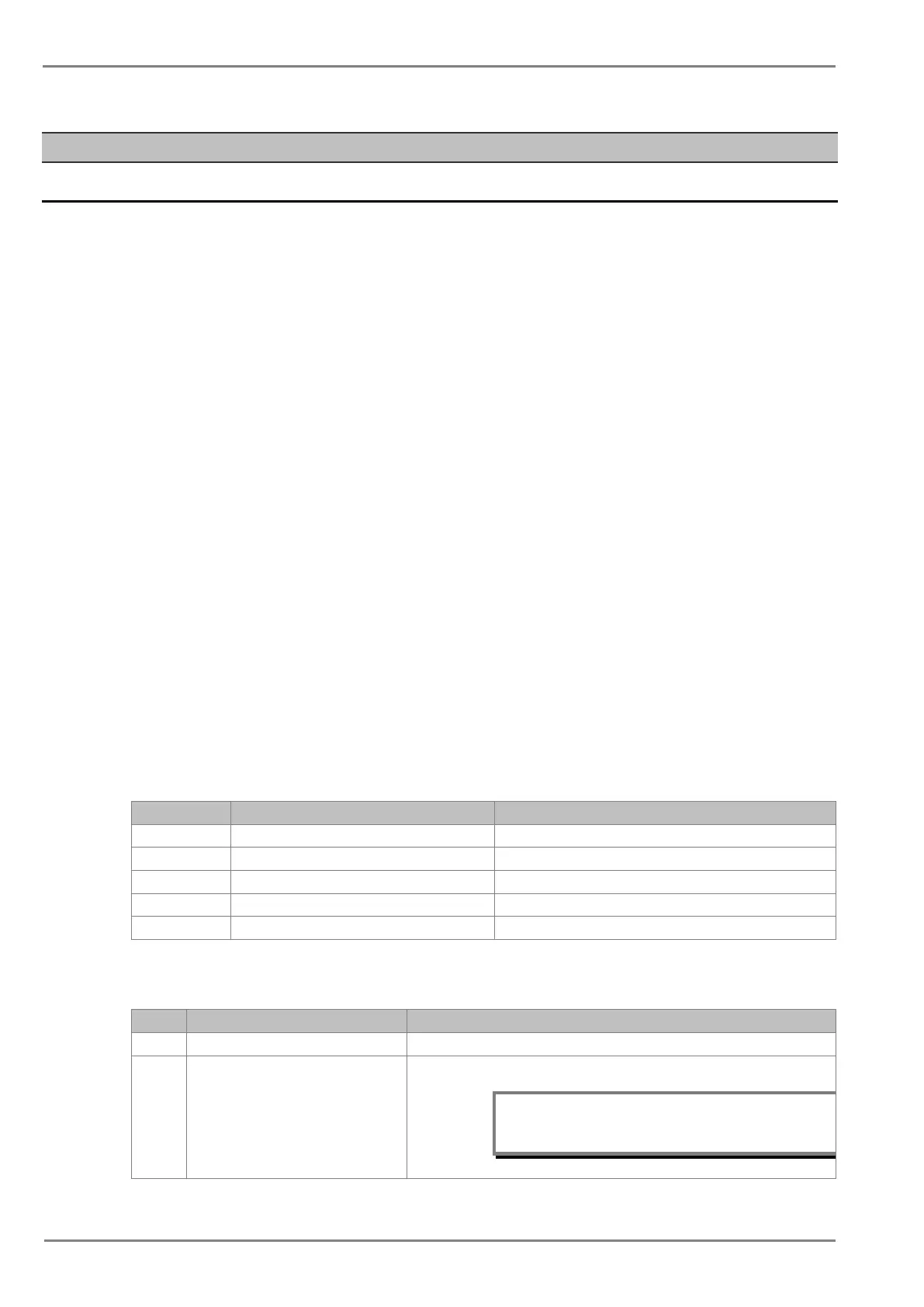
The following MODBUS function codes are supported:
02 Read Input Status 1x addresses
03 Read Holding Registers 4x addresses
04 Read Input Registers 3x addresses
05 Force Single Coil 0x addresses
16 Preset Multiple Registers 4x addresses
• Exception Codes generated in case of an error:
Code MODBUS Response Name Product interpretation
01 Illegal Function Code The function code received in query is not supported by the IED.
02 Illegal Data Address The start address received in the query is not an allowable value.
Note: If the start address received is correct but
the range includes unsupported address,
then this error is produced.
 Loading...


