13 Commissioning Instructions
2. Apply a current of twice the setting shown in the I>1 Current Set cell in the OVERCURRENT
menu.
3. Note the time displayed when the timer stops.
4. Check that the red trip LED has illuminated.
2.1.11.4 Checking the Operating time
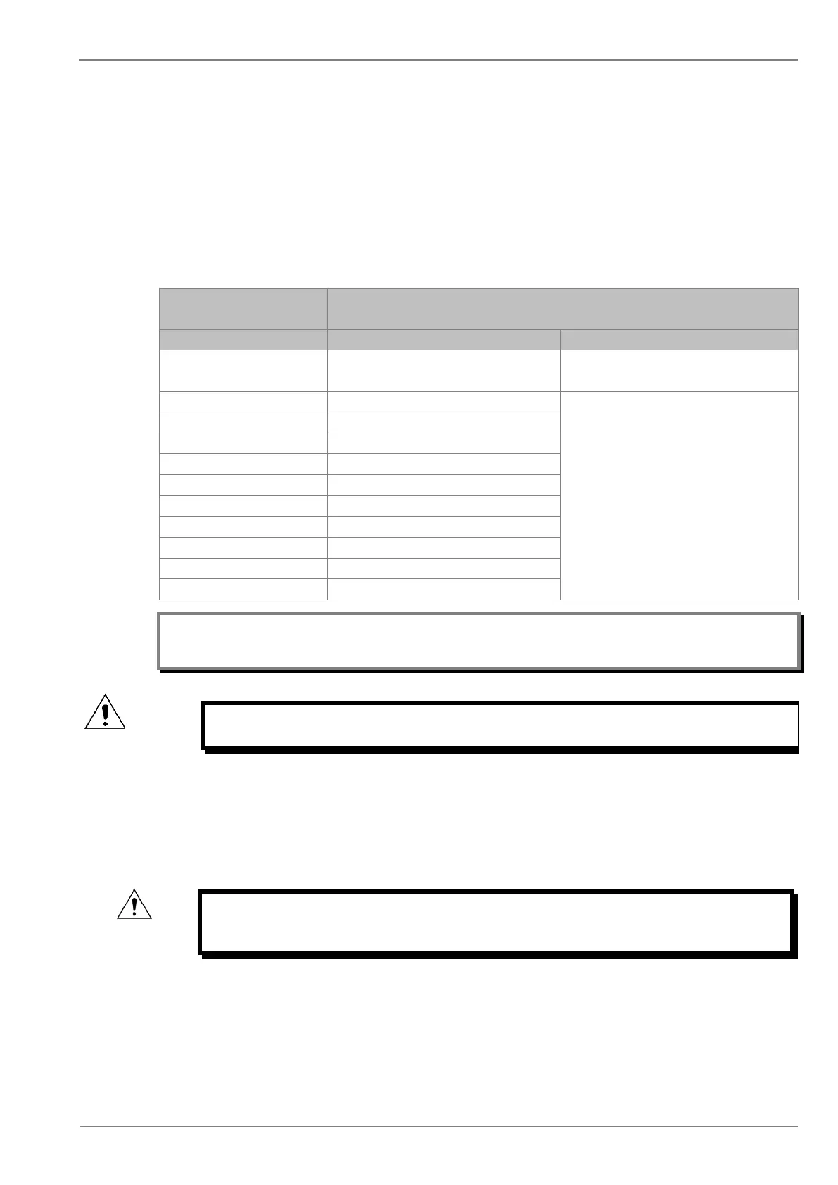
Check that the operating time recorded by the timer is within the range shown below.
For all characteristics, allowance must be made for the accuracy of the test equipment being used.
Characteristic
Operating time at twice current setting and time multiplier/
DT I>1 Time Delay setting
Setting ±5% or 55ms whichever is greater*
(*Fault current 2 times the set value)
IEC S Inverse 10.03
Please refer to the Technical Specifications
chapter for operating time accuracy
UK LT Inverse 20.00
IEEE M Inverse 3.8
IEEE V Inverse 7.03
US ST Inverse 12.12
Note: With the exception of the definite time characteristic, the operating times given are for a Time
Multiplier Setting (TMS) or Time Dial Setting (TDS) of 1. For other values of TMS or TDS, the values
need to be modified accordingly
Caution: On completion of the tests, you must restore all settings that were
disabled
2.1.12 Onload checks
Onload checks can only be carried out if there are no restrictions preventing the energisation of the
plant, and the other devices in the group have already been commissioned.
Remove all test leads and temporary shorting links, then replace any external wiring that has been
removed to allow testing.
Caution: If any external wiring has been disconnected for the commissioning
process, replace it in accordance with the relevant external
connection or scheme diagram.
2.1.12.1 Onload checks
1. Measure the current transformer secondary values for each input using a multimeter
connected in series with the corresponding current input.
 Loading...


