Home
GE
Circuit breakers
AKR Series
GE AKR Series User Manual
5
of 1
of 1 rating
32 pages
Give review
Manual
Specs
To Next Page
To Next Page
MAINTENANCE
MANUAL
(SUPPLEMENT)
GEI-86134D
(Supplement
to
GEK-731
0)
POWENCINCuIT
BNEAKENS
TYPE
AKR
This
manual
when
used
in
conjunction
with
Publication
GEK-7310
(Main-
tenance
Manual
for
AKR-3/3A-50
and
AKRU-3A-50
breakers)
provides
main-
tenance
instructions
on
the
AKR
breaker
models
and
trip
devices
listed
in
Table
1.
IAB]T
I
Frame
Size
(Amp)
Breaker
Type
&
Mounting
Trip
Device
Type
Stationarv
Drawout
ECS
ssr
800
AKR-4-30,
30H
AKR-4A-30,
3OH
X
AKR-5-30,
30H
AKR-5A-30.
30H
x
AKRU-4A-30*
X
AKRU-5A-30*
X
1600
AKR-4-50,
50H
AKR-4A-50,
50H
X
AKR-5-50,
50H
AKR-5A-50.
50H
X
AKRU-4A'-50*
x
AKRU-5A-50*
x
2000
AKRT-4-50
AKRT-4A-50
x
AKRT.5-50
AKRT-5A-50
X
*
-
Integrally
fused
types
GENERAL
@
ETECTRIC
2
Table of Contents
Table of Contents
2
Introduction
3
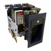
Rear Uiew of AKR-30 Breaker
3
Constructional Diff Erences
3
Breaker Ratings
4
Non-Interchangeability Hardware Arrangements
5
Slide Rail Rejection Pin Locations
5
Drawout Breaker Interchangeability
5
Contact Maintenance
6
Manual Handle Adjustment
6
Safety Precautions
6
AKR/AKRU-30 Contact Structure
7
Contact Adjustment
7
AKR-30 Wipe Adjustment
8
Contact Adjustment
8
AKRT- 50 Movable Contact Pivot Block
9
AKRT-50 Contact Structure
9
AKRU-30/50 Fused Breakers
10
Contact Replacement
10
Fuse Sizes and Mounting
10
GE CLF Fuses for AKRU Breakers
10
Mounting of Class J Fuses on AKRU-30 Breakers
11
Typical Mounting for Class L Fuse
11
AKRU-|0 Breaker with Special 2500A Fuse
12
Open Fuse Lockout Device
12
Speciol 2500A Fuse for AKRU-50
12
Mounting for Special 2500A Fuse on AKRU-50 Breaker
13
Plan View of AKRU-50 Breaker Showing 2500A Fuse Tang Positions
13
SST Block Diagram
14
SST Programmer Unit
14
Breaker Maintenance
6
Type SST Overcurrent Trip Device T4
14
Components
14
AKR-54-30 Breaker with SST Trip Device
15
SST Trip Characteristics
16
SST Phase Sensor with Tap Board
16
SST Neutral Sensors
16
Troubleshooting
17
Neutral Sensor Secondary Disconnect Blocks
17
Using the SST Test Set
18
False Tripping
19
Replacement of Current Sensors
19
Flux Shift Trip Device
20
Flux Shift Trip Device Components
21
Trip Rod Adjustment
21
Cabling Diagram
22
Type ECS Overcurrent Trip Device
24
ECS Programmer Unit
24
ECS Block Diagram
24
Ecs Sst
24
ECS Trip Characteristics
25
ECS Current Sensors on AKRU-44-30 Breaker
25
Cabling Diagram for ECS Trip Device
26
ECS Current Sensor
26
5
Based on 1 rating
Ask a question
Give review
Questions and Answers:
Need help?
Do you have a question about the GE AKR Series and is the answer not in the manual?
Ask a question
GE AKR Series Specifications
General
Number of Poles
1, 2, 3
Voltage Rating
240V AC, 480V AC, 600V AC
Frame Size
AKR
Trip Unit
Thermal-Magnetic
Standards
UL, CSA
Amperage
Varies by model (15-1200)
Related product manuals
GE AKR
63 pages
GE AKR-50
63 pages
GE AKR-30
63 pages
GE AKR-75 Series
24 pages
GE AKR-30 Series
260 pages
GE AKR D 50H Series
260 pages
GE AK-15
28 pages
GE AK-50
32 pages
GE AKF-1C
7 pages
GE AK-2-15
10 pages
GE AK-2A-15
40 pages
GE AK-50 Series
48 pages