GEI-86134,
Power Circuit
Breqkers
TYPE
SST
OVERCURRENT
TRIP
DEVICE
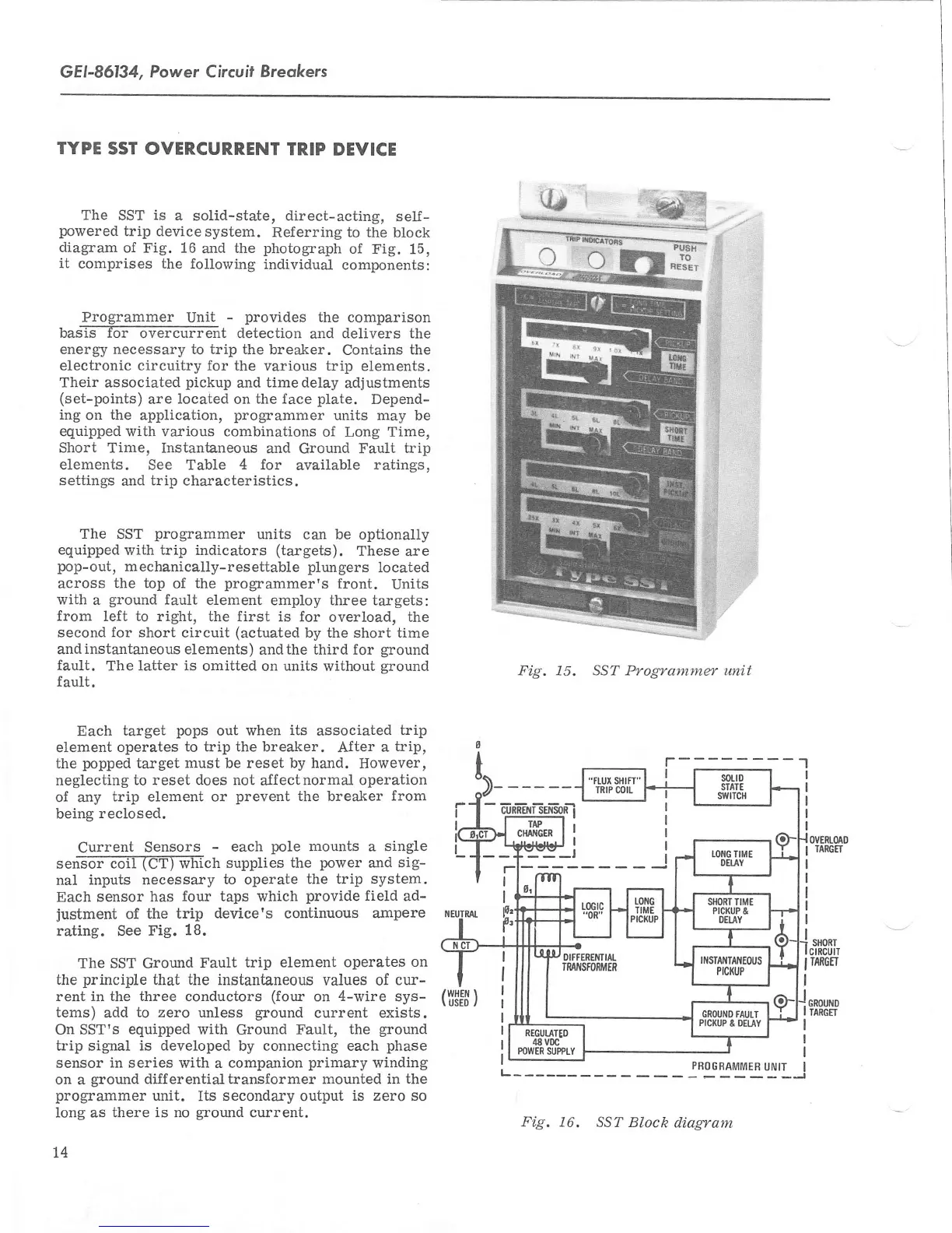
The
SST
is
a
solid-state, direct-acting,
self-
powered
trip
device
system.
Referring to the
block
diagram
of Fig.
16
and
the
photograph
of Fig.
15,
it
comprises the following
individual
components:
Programmer
Unit
-
provides
the
comparison
bas-is-T6T-6T6?6frrGnt
detection
and
delivers the
energ'y necessary to
trip
the
breaker.
Contains
the
electronic circuitry for
the various trip
elements.
Their
associated
pickup
and
timedelay
adjustments
(set-points)
are
located
on
the lace
plate.
Depend-
ing
on
the
application,
programmer
units
may
be
equipped rvith various combinations
of Long Time,
Short Time, Instantaneous
and
Ground Fault
trip
elements. See Table
4
for
available
ratings,
settings
and
trip characteristics.
The
SST
programmer
units can
be optionally
equipped
with trip indicators
(targets).
These
are
pop-out,
mechanically-resettable
plungers
Iocated
across
the top
of
the
programmer's
front.
Units
with
a
ground
fault
element
employ three targets:
from
left
to
right, the
first is for
overload, the
second for short
circuit
(actuated
by the
short time
andinstantaneous elements)
andthe
third for
ground
fault.
The latter is
omitted on
units
without
qround
fault.
Each
target
pops
out
when its
associated
trip
element
operates
to trip the breaker.
After
a
trip,
the
popped
target must
be
reset by hand.
However,
neglecting
to reset does not
aJfectnormal
operation
of any
trip element or
prevent
the breaker
from
being
reclosed.
Current
Sensors
-
each
pole
mounts a
single
senE5i-66II(ef)-EETch
supplies
the
power
and
sig-
nal
inputs necessa-ry
to operate
the trip
system.
Each
sensor has
four taps which
provide
field
ad-
justment
of the
trip
device's
continuous
ampere
rating. See Fig.
18.
The SST
Ground
Fault trip
element operates
on
the
principle
that the
instantaneous
vaLues of
cur-
rent in the three
conductors
(four
on
4-wire
svs-
tems)
add
to
zero unless
ground
current exists.
On
SST's equipped with
Ground
Fault,
the
ground
trip
signal
is developed
by connecting each
phase
sensor
in
series
with
a
companion
primary
winding
on a
ground
differentia-ltransformer mounted
in the
programmer
unit.
Its
secondary
output
is zero so
Iong as
there is no
ground
current.
l4
Fig. 15. SST Programmer unit
-1
r
I
-
I
([$F$
)
Fig.
16.
SST Block
diagrant
 Loading...