GEI-86134, Power Circvil Breokers
CONTACT
REPIACEIVIENf Types
AKR-30, 3OH
ond
AKRU-3O
The
stationary contacts
(arcing
and
mains)of the
AKR-30
breaker
frames
are replaced in
identical
fashion
to that
employed for the intermediate
and
main
stationary contacts
of
the AKR-50.
To
do
so,
however,
it is
necessary
to first remove the
arc
runner
by removing its three holding screws.
Replacement of
the
single movable
contact
arm
is
accomplished
in
like marurer
employed for the
AKR-50
breakers, i.e.,
remove
and
replace
the
coupling
pin, pivot pin,
etc.,
as
described
below.
CONTACT
REPTACEMENT Types AKR-SO,
50H,
AKRU-50
ond
AKRT-SO
Referring
to
Fig. 17 of
GEK-?310,
arcing
con-
tacts
(L)
are released by removing the
arc
runner
(5)
andthe
arcingcontact
pivot (6).
When reassem-
bling, make sure that the
insulating spacers on
the
ends of
the arcing
contact
pin (7)
and the insulating
',vashers
(B)
under the
lower arc runner
fastening
screws are
replaced.
Intermediate
(2)
and
main
contacts
(3)
are
re-
moved
by
disconnecting their
springs. The end
pieces
on the
springs
(9)
have
a
small hole for
in-
serting a spring
puller.
While holding the contact,
puII
the spring and lift it off
the
end of
the
contact.
Replace the contact by holding it in
position
(inner
end behind
the
contact stop) while extending and
engaging
the
spring on
the
outer
end. A suitable
puller
can be fashioned
by forming
a hook
on the
end of a
length
of. 1/76-tnch diameter
steel
wire.
The
two movable contact
arms
(4)
are removed
by drifting
out
pin
(10)
connecting
them to
the in-
sulated coupling
(11).
Right angle tru-arc pliers
are
needed to
remove and
replace the
tru-arc
re-
tainer
on
the
end of
the pin.
Next, remove the fastening
screws, washers,
springs
and
pivot
pin
from the
pivot
below. When
replacing the arms ensure that
all spacers, springs
and washers
are
returned totheir
original
position.
Tighten
the
two
bolts in the contact
arm
pivot.
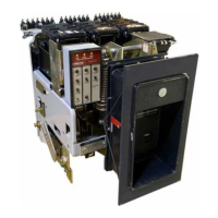
AKRU-3O ond
-50 FUSED BREAKERS
Except
for
the
open
fuse
lockout device
and
the
integrally-mounted fuses
on the
upper studs,
the
AKRU-30 and
-50
breakers
are
identical to the
un-
fused
AKR-30
and
-50
models.
Overcurrent
trip
devices
are
the
same
for
both types.
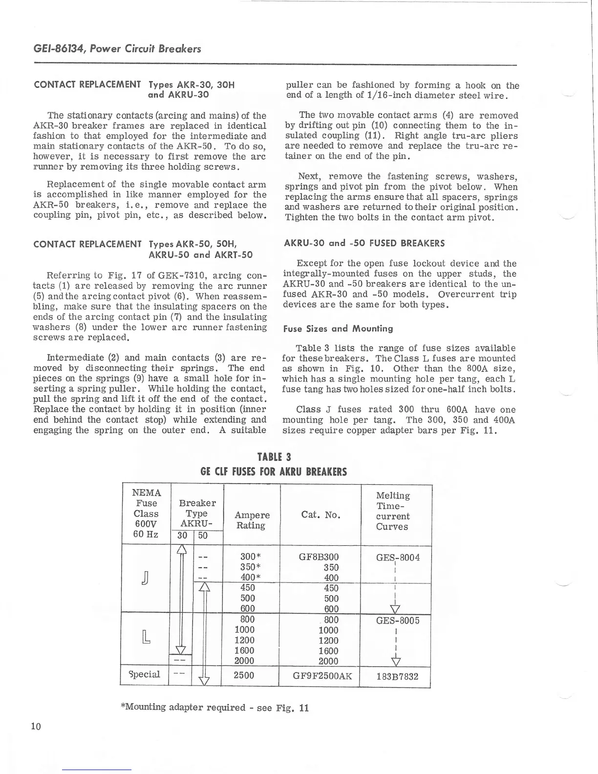
Fuse Sizes
ond Mounting
Table 3 lists
the range
of
fuse
sizes
available
for thesebreakers.
TheClass L
fuses
are
mounted
as shown
in
Fig. 10.
Other
than the
800A
size,
which has
a
single
mounting
hole
per
tang, each
L
fuse
tang has
two
holes sized
for
one-half
inch bolts.
Class J
fuses rated
300 thru 6004.
have
one
mounting hole
per
targ. The 300, 350
and
400A
sizes require copper adapter bars
per
Fig.
11.
IABIE
3
GT
CIT
rusTS
TOR ATRU BREAI(ERS
NEMA
Fuse
Class
600v
60
Hz
Breaker
Type
AKRU.
-5dl5o--
Ampere
Rating
Cat.
No.
Melting
Tine-
current
Curves
J
300x
3 50*
400x
GFSB3OO
350
400
GES
8004
ii
450
500
6no
450
500
600
I
I
I
V
L
800
1000
1200
1600
2000
.
800
1000
1200
1600
2000
GES-8005
I
I
I
I
V
Special
L 2500
GFgF2SOOAK
r.838?832
10
xMounting
adapter
required
-
see Fig.
11
 Loading...