Power
Circuil Breokers,
GEI-86134
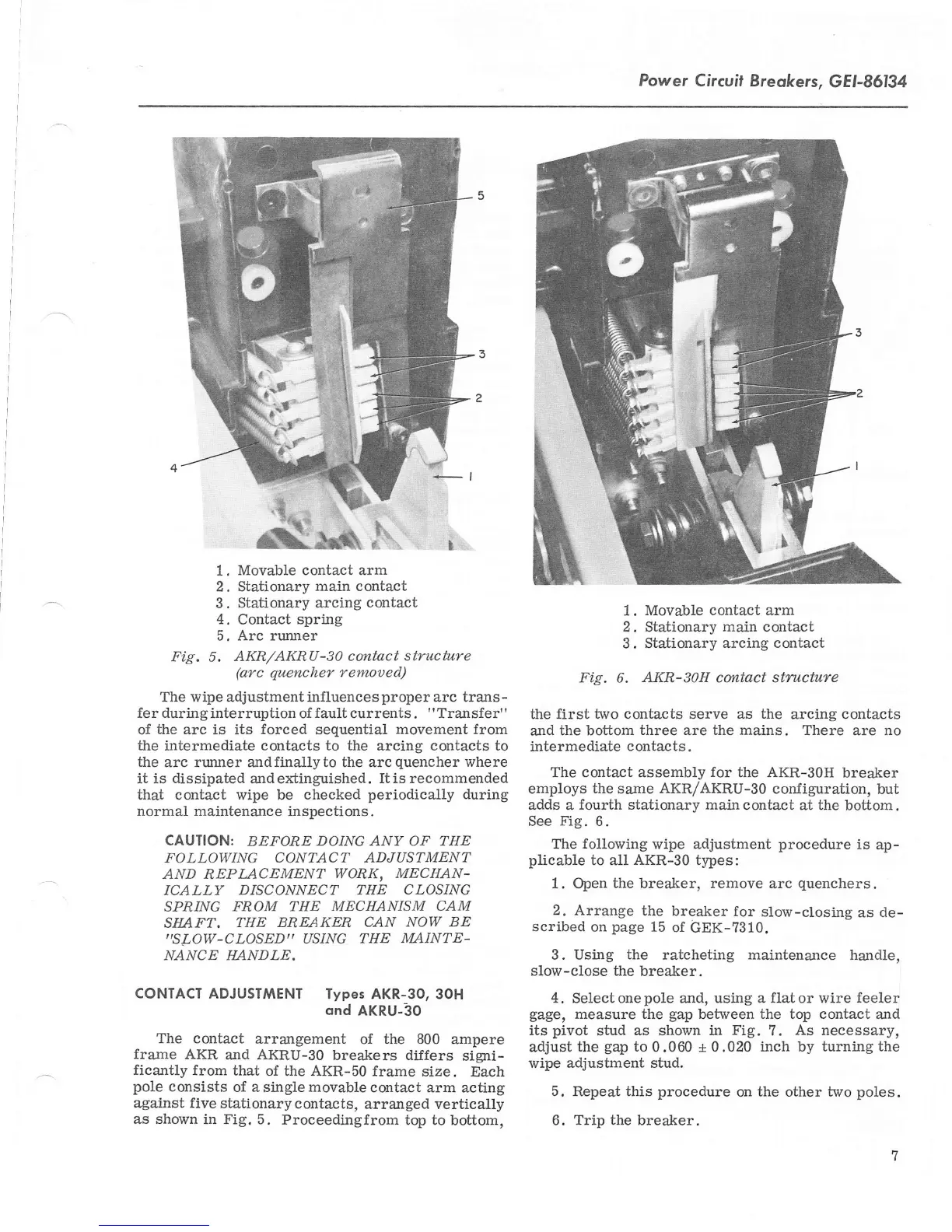
1.
Movable contact arm
2. Stationary
main contact
3.
Stationary arcing
contact
4.
Contact
spring
5. Arc runner
Fig.
5.
AKR/AKRU-S} contact
structure
(arc quencher
remoued)
The wipe adjustment influence s
proper
arc trans
-
fer during
interruption of
fault
currents
.
"
Transfer'
'
of
the
arc is its
forced
sequential
movement from
the intermediate contacts
to
the arcing contacts to
the
arc runner andfinallyto the arcquencher
where
it is
dissipated
andextinguished.
Itis recommended
that contact wipe be
checked
periodically during
normal maintenance
inspections.
CAUTION:
BEFORE
DOING ANY OF THE
FOLLOWING
CONTACT ADJUSTMENT
AND
REPLACEMBNT
WORK,
MECHAN-
ICALLY
DISCONNECT THE CLOSING
SPI1/NG
FROM THE MECHANISM
CAM
SIIAFT.
THE
BREAKER CAN
NOW BE
,,SLOW-CLOSEDI'
USING
THE
MAINTE-
NANCE HANDLE.
CONTACT
ADJUSITilENT Types
AKR-3O, 3OH
ond
AKRU-3O
The
contact
arrangement
of
the 800
ampere
frame
AKR
and AKRU-3O
breakers dilfers
signi-
ficantly
from
that
of the AKR-50
frame size.
Each
pole
consists
of a
single
movable
contact arm
acting
against five
stationary
contacts,
arranged vertically
as shown
in Fig. 5.
Proceedingfrom
top to
bottom,
1. Movable
contact
arm
2. Stationary
main
contact
3.
Stationary arcing
contact
Fig.
6.
AKR-S1H contact structure
the first two contacts serve as
the
arcing
contacts
and
the bottom
three
are
the mains.
There are no
intermediate
contacts.
The contact assembly
for
the AKR-30H
breaker
employs
the
same
AKR/AKRU-30
configuration,
but
adds a
fourth stationarv main
contact at the
bottom.
See
Fig.
6.
The
following
wipe
adjustment
procedure
is
ap-
plicable
to all
AKR-30
types:
1. Open
the breaker, remove
arc
quenchers.
2.
Arrange
the
breaker for
slow-closing
as de-
scribed
on
page
15
of
GEK-?310.
3. Using
the
ratcheting maintenance handle,
slow-close the
breaker.
4.
Se1ect one
pole
and,
using a flat or wire feeler
gage,
measure the
gap
between
the top contact
and
its
pivot
stud as shown
in Fig.
?.
As necessary,
adjust
the
gap
to
0.060 *
0.020 inch by turning the
wipe
adjustment stud.
5. Repeat this
procedure
on
the other two
poles.
6.
Trip the
breaker.
 Loading...