GEI-86134,
Power Circuit
Breqkers
I
BREAKER
\
\
CLOSED POSITION
/
ACTUATOR
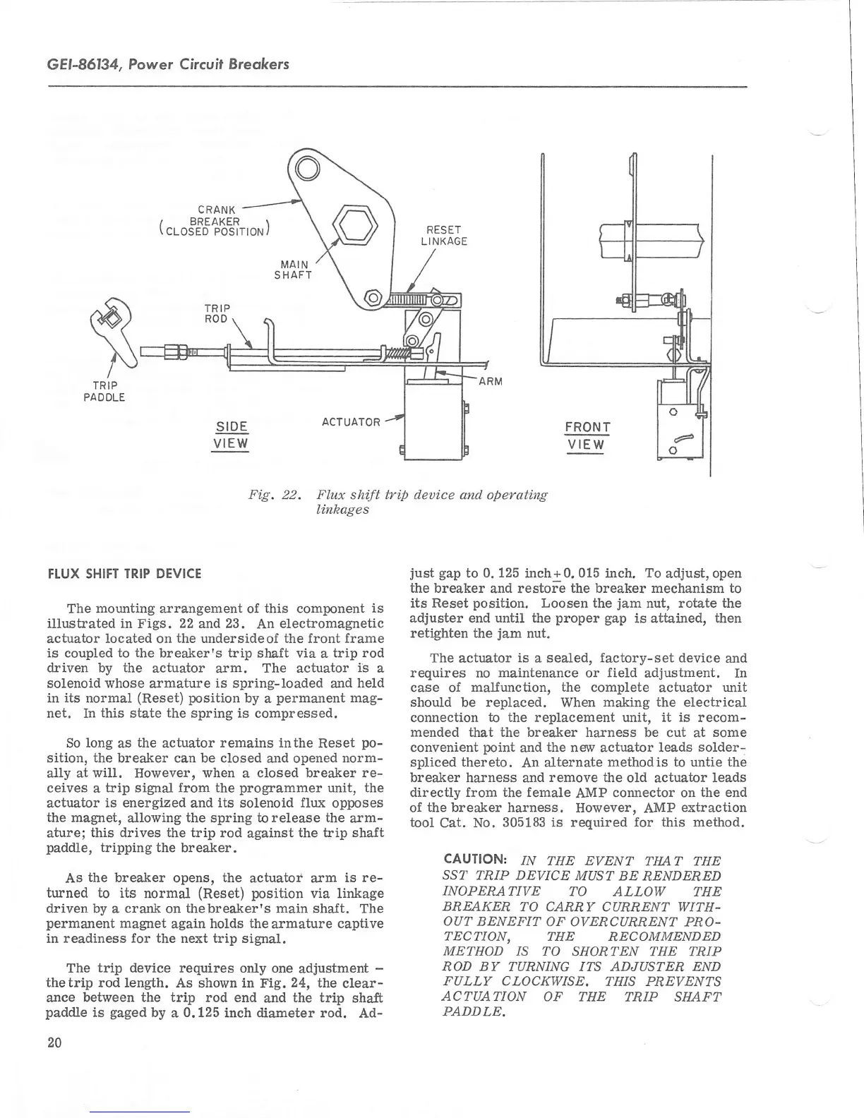
Fig.
22. Flux shi.ft trip deuice and operating
li.nkages
FLUX SHIFT TRIP DEVICE
The
mounting arrangement
of
this component
is
illustrated in Figs. 22 and23.
An
electromagnetic
actuator
located
on
the
undersideof the front frame
is coupled to
the
breaker's trip
shaft
via
a
trip rod
driven
by
the
actuator
arm.
The
acfuator
is
a
solenoid whose
armature
is spring-loaded
and
held
in
its
normal
(Reset)
position
by
a
permanent
mag-
net. In
this
state
the
spring is compressed.
So
long
as
the
acfuator
remains inthe
Reset
po-
sition, the breaker can be closed
and opened
norm-
ally
at will.
However,
when
a
closed breaker re-
ceives
a
bip signal from the
programmer
unit, the
actuator
is energized
and
its solenoid flux
opposes
the magnet,
allowing
the spring to release the
arm-
ature;
this drives the trip
rod
against
the trip
shaft
paddle,
tripping the
breaker.
As
the
breaker
opens,
the
actuator arm
is
re-
turned to its
normal
(Reset) position
via linkage
driven by
a
crank on thebreaker's main sha-ft.
The
permanent
magnet
again
holds
the
armature
captive
in
readiness for
the next trip signal.
The
trip device requires
only one
adjustment
-
thetrip rod length. As
shown
in
Fig.
24,
the
clear-
ance
between the trip rod
end
and
the trip
shaft
paddle
is
gaged
by
a
0.125
inch diameter rod.
Ad-
20
just
gap
to
0. 125
inch+ 0. 015 inch.
To
adjust,
open
the breaker
and restore
the breaker mechanism to
its Reset
position.
Loosen the
jam
nut, rotate the
adjuster
end
until
the
proper gap
is attained, then
retighten the
jam
nut.
The
actuator
is
a sealed,
factory-set
device
and
requires
no
maintenance
or
field
adjustment. In
case of malfunction,
the
complete actuator
unit
should be replaced.
When
making
the electrical
connection
to
the replacement unit, it
is
recom-
mended that the breaker harness
be cut
at
some
convenient
point
and
the
new actuator leads
solder-
spliced
thereto.
An
afternate
methodis to untie the
breaker harness and
remove the
old
actuator
leads
directly from the female
AMP
connector on
the end
of
the breaker harness.
However.
AMP
extraction
tool
Cat.
No.
305183 is required for
this method.
CAUTION:
IN
THE EVENT
TIIAT THE
SST TRIP DEVICE
MUST BE
RENDERED
INOPERATIVE
TO
ALLOW THE
BREAKER
TO
CARRY CURNENT WITH-
OUT
BENEFIT
OF OVERCURRENT
PRO-
TECTION, THE
RECOMMENDED
METHOD /S TO
SHORTEN THE TRIP
ROD
BY
TURNING ITS ADJUSTEN END
FULLY
CLOCKWISE.
THIS PREVENTS
ACTUATION
OF THE
TRIP SHAFT
PADDLE,
 Loading...