OUTDOOR UNIT CONTROLS and COMPONENTS
PAGE 10
ENGLISH
Terminal Block
Power Factor Reactor
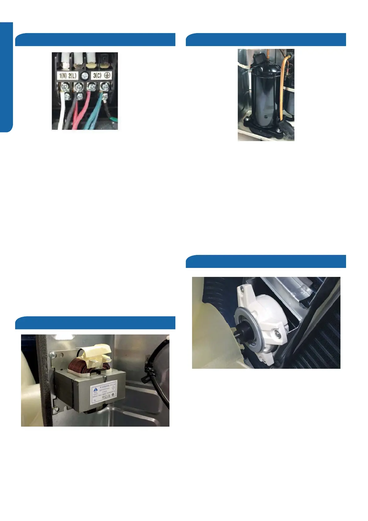
Compressor
Fan Motor
The 18K and 24K units are 208/230 volt single phase. The
9K and 12K units are 120 volt. All models use terminals 1
and 2 as incoming power wiring. Number 3 is the
communication terminal and the 4th terminal is the ground
connection. Be sure to match this wiring with the indoor
unit terminals.
External accessories such as a condensate overflow switch
should break the number 2 (line) terminal.
The indoor unit is powered from the same source as the
outdoor section and is connected by using 14/4 AWG
copper wire.
There should be no splices in the wiring between the indoor
and outdoor unit.Splices may create a loss of communication
and generate an E7 error code.
The Reactor is an inductive filter that will aid in correction of
electrical power factor influence of inverter capacitance. It is
unlikely to ever have an electrical failure of this component.
The Reactor is electrically connected to the IPM on terminals
CN6 and CN7 (09k and 12k), or CN3 and CN4 (18k and 24k)..
The compressor is a three phase DC inverter-driven rotary.
The compressor is capable of variable speed operation.
The operating frequency will be determined by the difference
between set point and room emperature.
The compressor is electrically connected to the Module
Board on terminal connections CN-2, CN-3 and CN-4.
The compressor has an internal temperature overload that
will open if the compressor becomes too hot. Additional
protection of the compressor will be provided by the
Compressor Discharge Temperature Sensor and Suction
Line Temperature Sensor.
The fan motor is a variable speed DC motor,The required
motor speed is calculated by the Main Control Board.
The motor is electrically connected to the PCB via
CN21 (09k and 12k), or CN22 (18k and 24k).
In COOL MODE , the motor will slow down as outdoor air
temperature falls. In HEAT MODE, the motor will increase
speed as the outdoor air temperature falls.
 Loading...