Troubleshooting
Start
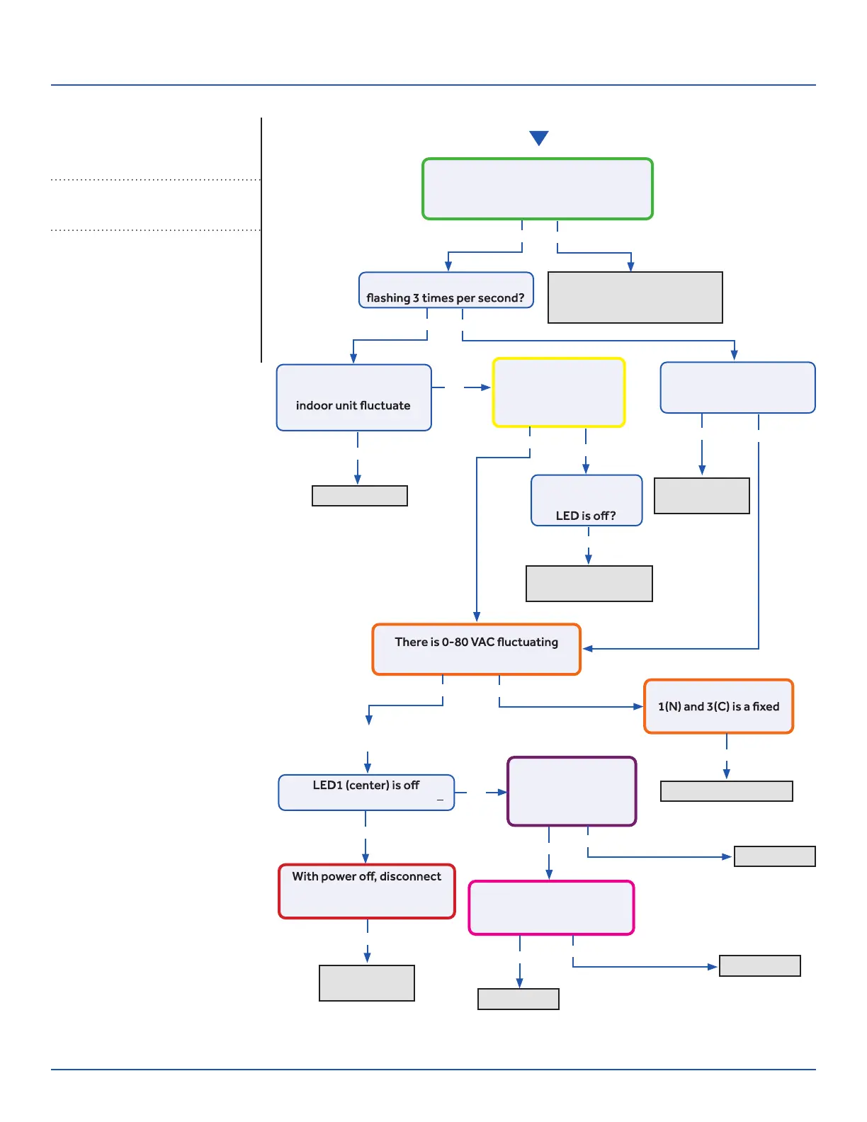
See reverse side for
wiring diagram and
relevant color-coded
test positions.
Reposition on correct
terminals, replace wire if
spliced or the incorrect type
Indoor PCB OK
The control wire is 14/4 stranded
copper on the correct terminals, with
no splices or loose connections?
Yes
No
Yes
Yes
No
No
Is the Indoor PCB LED
Does the voltage
between L and C at
0~140VAC?
Is the voltage from
L to C at indoor unit
between 0~80VAC
(approx..)?
Is the Indoor PCB LED
pattern repeatedly
Flash…Flash…On?
Fault is with
outdoor PCB
Replace fan
motor
Replace INDOOR PCB
Replace PCB
Replace PCB
Replace IPM
The communication
wire is broken
between 1(N) and 3(C) at ID UNIT?
There is 230 VAC
at the PCB? Across
AC-L OUT & AC-N
OUT (CN9 & CN8)
There is less than 5 VDC at
CN22 (module power) and
GND (pins 1 and 2)?
The voltage between
value at ID UNIT?
Go to outdoor PCB
No
Yes
Yes
Yes
Yes
Yes
Yes
Yes
No
No
Yes
Yes
No
No
No
LED2 (upper left) is lighted?
fan motor at CN21. LED1
lights with power back on?
The display is
lighted, yet the
Error Code (Indoor/Outdoor)
E7/LED1: 15 Flash
ID and OD Loss of Communication
Complete the “Check This First” Flow
Chart for both ID and OD units before
continuing.
Models:
ERROR CODES and Troubleshooting
PAGE 48
ASYW09CRAWA
ASYW12CRAWA
ASYW18CRDWA
ASYW24CRDWA
ASH109CRAWA
ASH112CRAWA
ASH118CRAWA
ASH124CRAWA
 Loading...