© 2007 by General Electric Company. All rights reserved. M1110150 006 17
Chapter 5: Replacement/Checkout Procedures
Electrical Safety Checkout Procedure
Use approved equipment and techniques to test the unit’s leakage current and ground continuity. Follow the directions
supplied by the test equipment manufacturer to verify the following:
Leakage Current
Less than 300 microamperes measured at any exposed metal surface.
Ground Resistance Check Measure the resistance between the ground pin on the line cord plug and exposed metal
of the light box. The ground resistance must be less than
0.1 ohms.
Light Intensity Checkout Procedure
1. Fully insert the beroptic light pad connector into the light box.
WARNING:
When handling the beroptic cable connector (during insertion, removal or positioning of the
beroptic light pad) use caution to prevent the beroptic cable connector from dropping, which
can damage the beroptic cable connector and/or injure the patient or caregiver.
2. Connect the power cord to the back of the unit, then to an appropriately grounded power source.
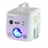
3. Turn the BiliSoft LED Phototherapy System on using the standby switch on the front of the unit and allow it
to run for ve (5) minutes.
4. Place the beroptic light pad on a at surface. Do not place the beroptic light pad inside of the BiliSoft Pad
Cover or BiliSoft Nest at this time.
5. Use a properly-calibrated Ohmeda Medical BiliBlanket Meter II to check the irradiance level of the unit using
the template printed on the beroptic light pad. There are two ways to check the irradiance level - a center-
row quick check, which provides approximate irradiance values, and the more comprehensive 6-point (for
small beroptic light pad) or 9-point (for large beroptic light pad) check, which provides more accurate
irradiance values.
To perform the center-row check, measure the irradiance level at each point on the center row using the
template printed on the beroptic light pad. For a small pad, the center row points are C and D. For the large
pad, the center row points are D, E and F. Calculate the average of the center row irradiance measurements.
Use the rst column of the chart below to determine if the minimum acceptable center-row irradiance has
been met. If the average of the light meter readings meets or exceeds the acceptable minimum irradiance,
then the unit is ready for use.
If the meter readings are lower than these values, perform the more comprehensive 6-point (small pad)
or 9-point (large pad) check. Measure the irradiance level at each point using the template printed on the
beroptic light pad. Calculate the average of the irradiance measurements. Use the second column of the
chart below to determine if the average irradiance is within specication. If the average irradiance is outside of
the acceptable range, see the troubleshooting section of this manual.
 Loading...