g
GE
OPM_SGS_ISG_10K_40K_0US_V010.doc 34/45 Installation Guide SG Series 10, 20, 30 & 40 kVA
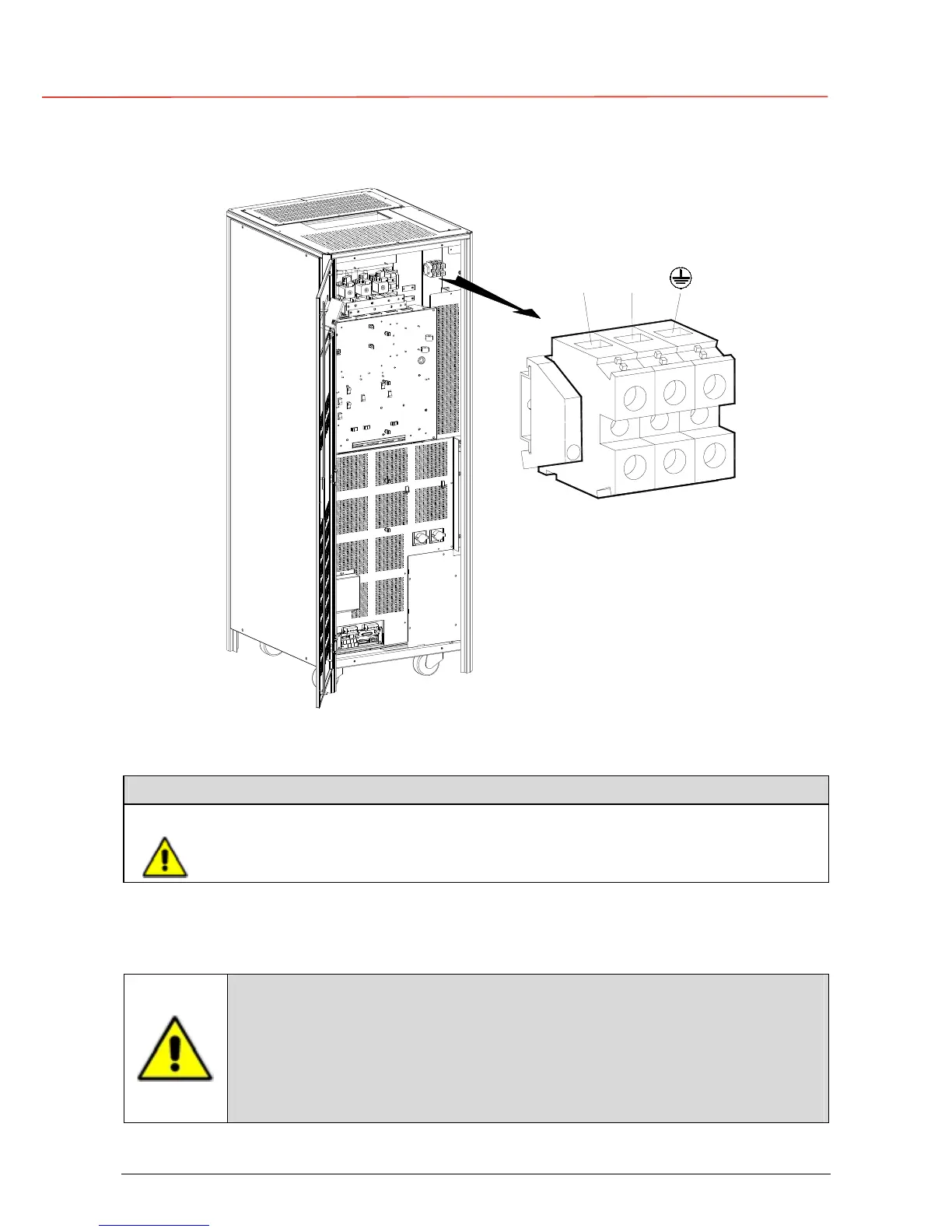
3.8.7 Battery connection of SG Series 30 and 40 kVA
SGT5000_030-040_UPS connection battery_01US
BATTERY
X3
+
PE
_
Fig. 3.8.7-1 Power connections battery of SG Series 30 and 40 kVA
SG Series 30 and 40 kVA: Max. rating Battery terminals: 1 AWG (50mm
2
)
Battery
+
Positive pole of the Battery
–
Negative pole of the Battery
Do not insert the Battery Fuses before the commissioning.
Battery cable terminations are to the Positive and Negative Terminals as shown above.
Connect wire to the Terminals using appropriate tools and appropriate torque.
Torque specification for Input / Output and DC power connections on Terminals: See sect.. 3.8.1.
To meet standards concerning electromagnetic compliance, the connection
between the UPS and external battery must be done by using a shielded
cable or suitable shielded (metal) conduit!
This UPS is only designed to operate in a wye-configured electrical system
with a solidly grounded neutral.
If the UPS is equipped with an input transformer for, the secondary of the
transformer must be wye-configured with neutral solidly grounded.
 Loading...


