CHAPTER 5: SETTINGS PRODUCT SETUP
F35 MULTIPLE FEEDER PROTECTION SYSTEM – INSTRUCTION MANUAL 5-155
5
The data logger samples and records up to 16 analog parameters at a user-defined sampling rate. This recorded data can
be downloaded to EnerVista UR Setup and displayed with parameters on the vertical axis and time on the horizontal axis.
All data is stored in non-volatile memory, so the information is retained when power to the relay is lost.
For a fixed sampling rate, the data logger can be configured with a few channels over a long period or a larger number of
channels for a shorter period. The relay automatically partitions the available memory between the channels in use. The
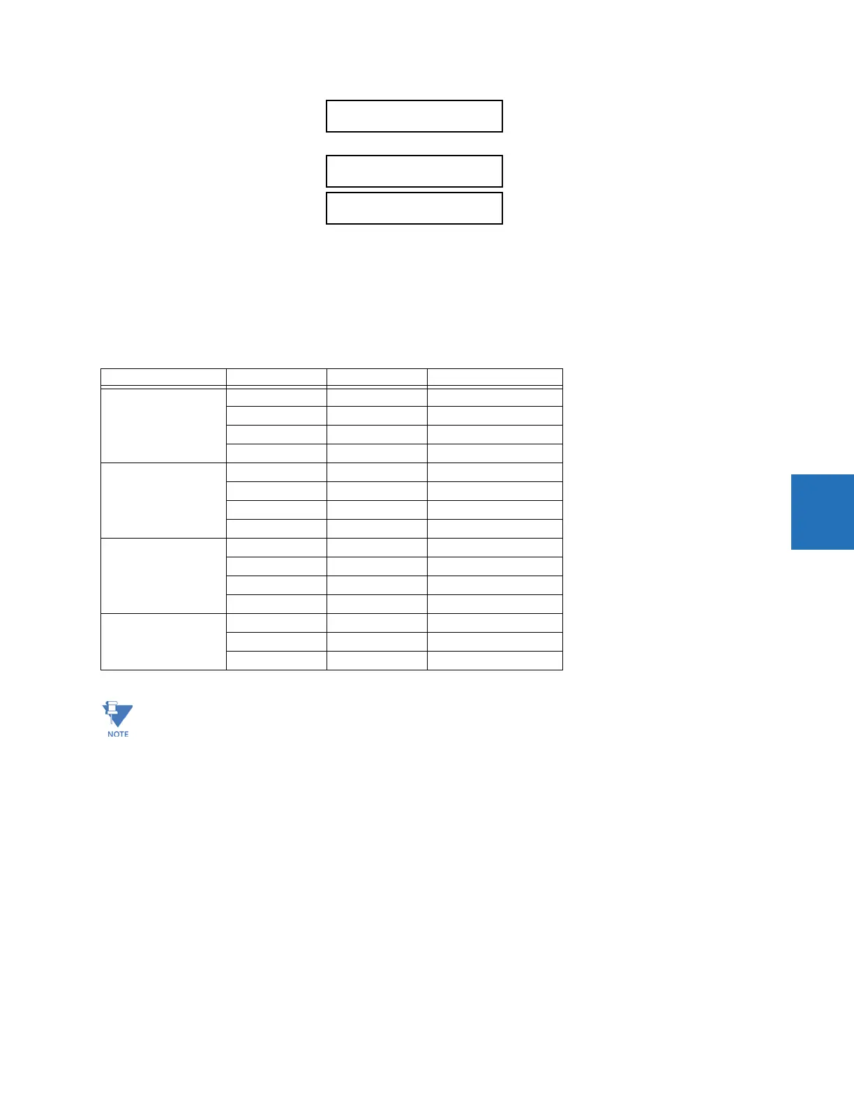
following table outlines examples of storage capacities for a system frequency of 60 Hz.
Table 5-16: Data logger storage capacity example
DATA LOGGER MODE — This setting configures the mode in which the data logger operates. When set to “Continuous,” the
data logger actively records any configured channels at the rate as defined by the DATA LOGGER RATE. The data logger is
idle in this mode when no channels are configured. When set to “Trigger,” the data logger records any configured channels
at the instance of the rising edge of the
DATA LOGGER TRIGGER source FlexLogic operand. The data logger ignores all
subsequent triggers and continues to record data until the active record is full. Once the data logger is full, a CLEAR DATA
LOGGER command is required to clear the data logger record before a new record can be started. Performing the CLEAR
DATA LOGGER command also stops the current record and resets the data logger to be ready for the next trigger.
DATA LOGGER TRIGGER — This setting selects the signal used to trigger the start of a new data logger record. Any FlexLogic
operand can be used as the trigger source. This setting only applies when the mode is set to “Trigger.”
DATA LOGGER RATE — This setting selects the time interval at which the actual value data is recorded.
DATA LOGGER CHNL 1(16) — This setting selects the metering actual value that is to be recorded in Channel 1(16) of the data
log. The parameters available in a given relay are dependent on: the type of relay, the type and number of CT/VT hardware
modules installed, and the type and number of Analog Input hardware modules installed. Upon startup, the relay
automatically prepares the parameter list. A list of all possible analog metering actual value parameters is shown in
DATA LOGGER CHNL 1:
Off
Range: Off, any FlexAnalog/actual value parameter
See Appendix A for list
DATA LOGGER CHNL 16:
Off
Range: Off, any FlexAnalog/actual value parameter
See Appendix A for list
DATA LOGGER CONFIG:
0 CHNL x 0.0 DAYS
Range: Not applicable - shows computed data only
Sampling rate Channels Days Storage capacity
15 ms 1 0.1 482 s
80.160s
90.154s
16 0.1 30 s
1000 ms 1 0.3 32729 s
8 0.1 4091 s
9 0.1 3637 s
16 0.1 2046 s
60000 ms 1 22.7 1963710 s
8 2.8 245460 s
9 2.5 218190 s
16 1.4 127230 s
3600000 ms 1 1362.1 117822600 s
8 170.2 14727600 s
9 151.3 13091400 s
Changing any setting affecting data logger operation clears data in the log.

 Loading...


