CHAPTER 5: SETTINGS PRODUCT SETUP
F35 MULTIPLE FEEDER PROTECTION SYSTEM – INSTRUCTION MANUAL 5-157
5
5.3.11.2 Calculation method 2: Block interval
This method calculates a linear average of the quantity (RMS current, real power, reactive power, or apparent power) over
the programmed demand time interval, starting daily at 00:00:00 (that is, 12:00 am). The 1440 minutes per day is divided
into the number of blocks as set by the programmed time interval. Each new value of demand becomes available at the
end of each time interval.
5.3.11.3 Calculation method 2a: Block interval (with start demand interval logic trigger)
This method calculates a linear average of the quantity (RMS current, real power, reactive power, or apparent power) over
the interval between successive Start Demand Interval logic input pulses. Each new value of demand becomes available at
the end of each pulse. Assign a FlexLogic operand to the
DEMAND TRIGGER setting to program the input for the new
demand interval pulses.
5.3.11.4 Calculation method 3: Rolling demand
This method calculates a linear average of the quantity (RMS current, real power, reactive power, or apparent power) over
the programmed demand time interval, in the same way as Block Interval. The value is updated every minute and
indicates the demand over the time interval just preceding the time of update.
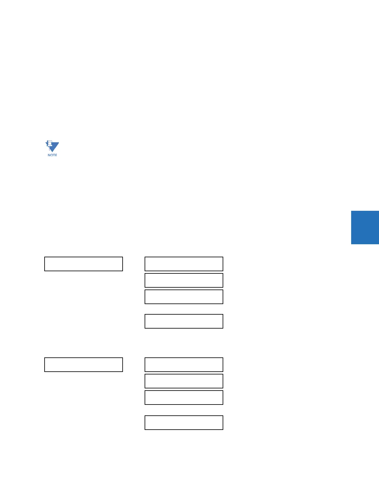
5.3.12 User-programmable LEDs
5.3.12.1 Menu - Enhanced and standard front panels
SETTINGS PRODUCT SETUP USER-PROGRAMMABLE LEDS
5.3.12.2 Menu - Graphical front panel
SETTINGS PRODUCT SETUP USER-PROGRAMMABLE LEDS
If no trigger is assigned in the
DEMAND TRIGGER setting and the CRNT DEMAND METHOD is "Block Interval," use
calculation method 2. If a trigger is assigned, the maximum allowed time between two trigger signals is 60 minutes.
If no trigger signal appears within 60 minutes, demand calculations are performed and available, and the algorithm
resets and starts the new cycle of calculations. The minimum required time for trigger contact closure is 20 µs.
USER-PROGRAMMABLE
LEDS
LED TEST
See below
TRIP & ALARM LEDS
See page 5-160
USER-PROGRAMMABLE
LED 1
See page 5-160
USER-PROGRAMMABLE
LED 48
USER-PROGRAMMABLE
LEDS
LED TEST
See below
TRIP & ALARM LEDS
See page 5-160
EVENT CAUSE LED 1
See page 5-161
EVENT CAUSE LED 9

 Loading...


