CHAPTER 5: SETTINGS CONTROL ELEMENTS
F35 MULTIPLE FEEDER PROTECTION SYSTEM – INSTRUCTION MANUAL 5-279
5
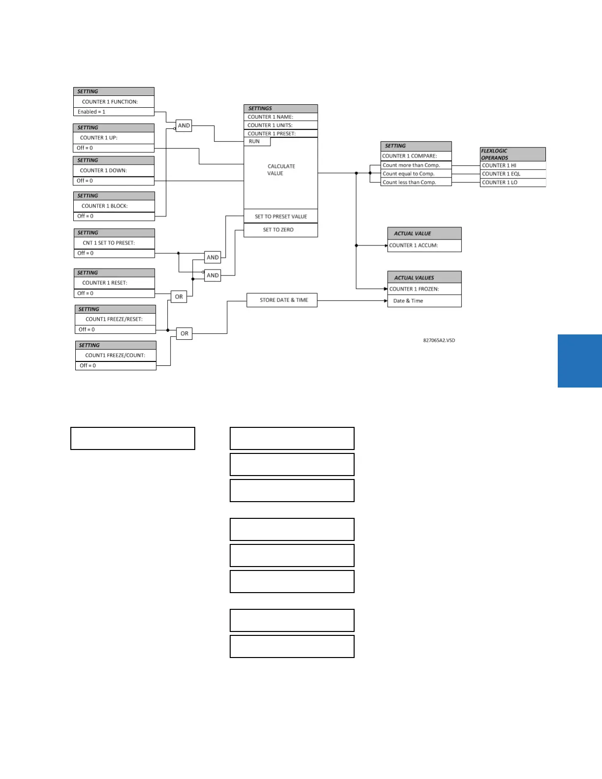
Figure 5-153: Digital counter logic
5.8.9 8-bit switches
SETTINGS CONTROL ELEMENTS 8-BIT SWITCHES 8-BIT SWITCH 1(6)
This feature allows switching between two input arguments defined by 8 bits each. The bits are specified by FlexLogic
operands. The feature could be viewed as an integrated two-position switch for 8 logic signals.
Typically this element is applied in conjunction with the Digitizer and 8-bit Comparator features.
8-BIT
SWITCH 1
8BIT SWITCH 1
FUNCTION: Disabled
Range: Disabled, Enabled
8BIT SW 1 ARG A0:
Off
Range: FlexLogic operand
8BIT SW 1 ARG A1:
Off
Range: FlexLogic operand
8BIT SW 1 ARG A7:
Off
Range: FlexLogic operand
8BIT SW 1 ARG B0:
Off
Range: FlexLogic operand
8BIT SW 1 ARG B1:
Off
Range: FlexLogic operand
8BIT SW 1 ARG B7:
Off
Range: FlexLogic operand
8BIT SW 1 CONTROL:
Off
Range: FlexLogic operand

 Loading...


