5-160 F35 MULTIPLE FEEDER PROTECTION SYSTEM – INSTRUCTION MANUAL
PRODUCT SETUP CHAPTER 5: SETTINGS
5
5.3.12.4 Trip and alarm LEDs
SETTINGS PRODUCT SETUP USER-PROGRAMMABLE LEDS TRIP & ALARMS LEDS
The trip and alarm LEDs are in the first LED column (enhanced and graphical front panels) and on LED panel 1 (standard
front panel). Each LED can be programmed to turn on when the selected FlexLogic operand is in the logic 1 state.
5.3.12.5 User-programmable LED 1(48)
SETTINGS PRODUCT SETUP USER-PROGRAMMABLE LEDS USER-PROGRAMMABLE LED 1(48)
For the enhanced and standard front panels, there are 48 amber LEDs across the relay LED panels. Each of these
indicators can be programmed to illuminate when the selected FlexLogic operand is in the logic 1 state.
For the standard front panel, the LEDs are located as follows:
• LED Panel 2 — User-programmable LEDs 1 through 24
• LED Panel 3 — User programmable LEDs 25 through 48
For the enhanced front panel, the LEDs are located as follows:
• LED column 2 — User-programmable LEDs 1 through 12
• LED column 3 — User-programmable LEDs 13 through 24
• LED column 4 — User-programmable LEDs 25 through 36
• LED column 5 — User-programmable LEDs 37 through 48
See the LED Indicators section in chapter 4 for information on the location of these indexed LEDs.
The user-programmable LED settings select the FlexLogic operands that control the LEDs. If the
LED 1 TYPE setting is “Self-
Reset” (the default setting), the LED illumination tracks the state of the selected LED operand. If the
LED 1 TYPE setting is
“Latched,” the LED, once lit, remains so until reset by the front panel
RESET button, from a remote device via a
communications channel, or from any programmed operand, even if the LED operand state de-asserts.
Table 5-17: Recommended settings for user-programmable LEDs
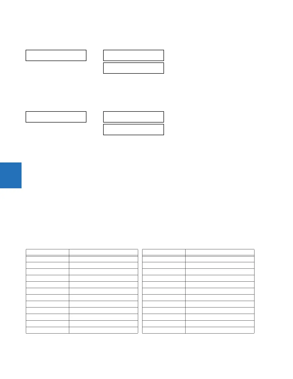
TRIP & ALARM LEDS
TRIP LED INPUT:
Off
Range: FlexLogic operand
ALARM LED INPUT:
Off
Range: FlexLogic operand
USER-PROGRAMMABLE
LED 1
LED 1 OPERAND:
Off
Range: FlexLogic operand
LED 1 TYPE:
Self-Reset
Range: Self-Reset, Latched
Setting Parameter Setting Parameter
LED 1 operand SETTING GROUP ACT 1 LED 13 operand Off
LED 2 operand SETTING GROUP ACT 2 LED 14 operand BREAKER 2 OPEN
LED 3 operand SETTING GROUP ACT 3 LED 15 operand BREAKER 2 CLOSED
LED 4 operand SETTING GROUP ACT 4 LED 16 operand BREAKER 2 TROUBLE
LED 5 operand SETTING GROUP ACT 5 LED 17 operand SYNC 1 SYNC OP
LED 6 operand SETTING GROUP ACT 6 LED 18 operand SYNC 2 SYNC OP
LED 7 operand Off LED 19 operand Off
LED 8 operand Off LED 20 operand Off
LED 9 operand BREAKER 1 OPEN LED 21 operand AR ENABLED
LED 10 operand BREAKER 1 CLOSED LED 22 operand AR DISABLED
LED 11 operand BREAKER 1 TROUBLE LED 23 operand AR RIP
LED 12 operand Off LED 24 operand AR LO

 Loading...


