CHAPTER 5: SETTINGS FLEXLOGIC
F35 MULTIPLE FEEDER PROTECTION SYSTEM – INSTRUCTION MANUAL 5-217
5
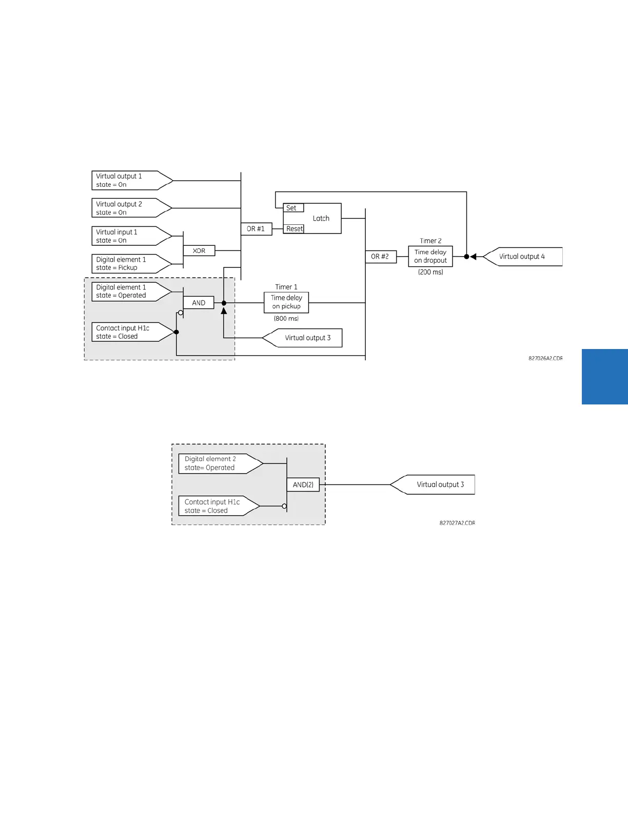
For the example shown, the output of the AND gate is used as an input to both OR#1 and Timer 1, and must therefore
be made a virtual output and assigned the next available number (that is, Virtual Output 3). The final output must also
be assigned to a virtual output as virtual output 4, which is programmed in the contact output section to operate relay
H1 (that is, contact output H1).
Therefore, the required logic can be implemented with two FlexLogic equations with outputs of virtual output 3 and
virtual output 4, shown as follows.
Figure 5-113: Logic example with virtual outputs
2. Prepare a logic diagram for the equation to produce virtual output 3, as this output is used as an operand in the virtual
output 4 equation (create the equation for every output that is used as an operand first, so that when these operands
are required they already have been evaluated and assigned to a specific virtual output). The logic for virtual output 3
is shown as follows with the final output assigned.
Figure 5-114: Logic for virtual output 3
3. Prepare a logic diagram for virtual output 4, replacing the logic ahead of virtual output 3 with a symbol identified as
virtual output 3, shown as follows.

 Loading...


