5-276 F35 MULTIPLE FEEDER PROTECTION SYSTEM – INSTRUCTION MANUAL
CONTROL ELEMENTS CHAPTER 5: SETTINGS
5
Assume the output contact H1 is a trip contact. Using the contact output settings, this output is given an ID name; for
example, “Cont Op 1." Assume a 52a breaker auxiliary contact is connected to contact input H7a to monitor breaker status.
Using the contact input settings, this input is given an ID name, for example, “Cont Ip 1," and is set “On” when the breaker is
closed. The settings to use digital element 1 to monitor the breaker trip circuit are indicated (EnerVista example shown).
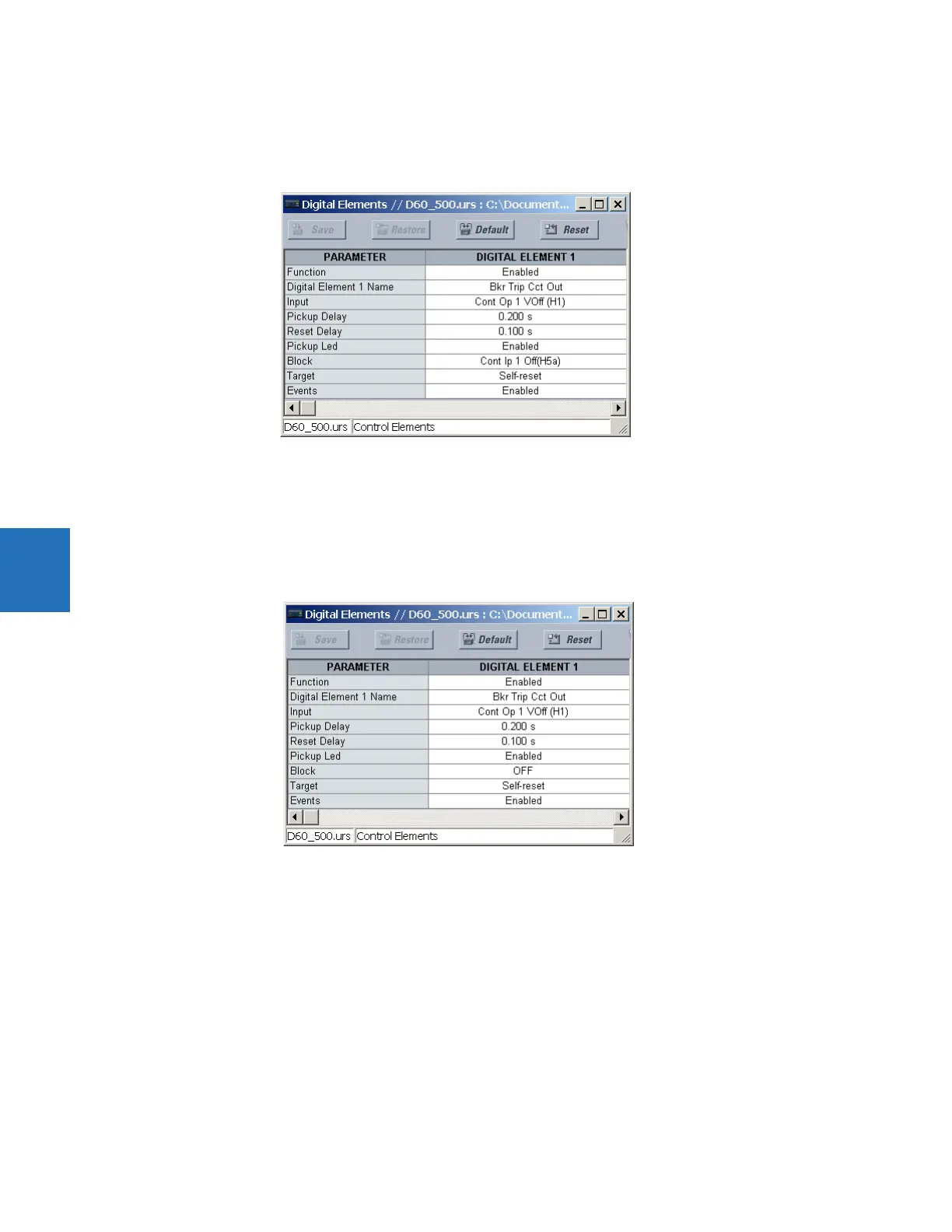
Example 2: Breaker trip circuit integrity monitoring
If it is required to monitor the trip circuit continuously, independent of the breaker position (open or closed), a method to
maintain the monitoring current flow through the trip circuit when the breaker is open must be provided (as shown in the
following figure). This can be achieved by connecting a suitable resistor (see figure) across the auxiliary contact in the trip
circuit. In this case, it is not required to supervise the monitoring circuit with the breaker position – the
BLOCK setting is
selected to “Off.” In this case, the settings are as follows (EnerVista example shown).

 Loading...


