9-2 F35 MULTIPLE FEEDER PROTECTION SYSTEM – INSTRUCTION MANUAL
FAULT LOCATOR CHAPTER 9: THEORY OF OPERATION
9
m = sought pu distance to fault
Z = positive sequence impedance of the line
I
F
= fault current flowing through the fault point
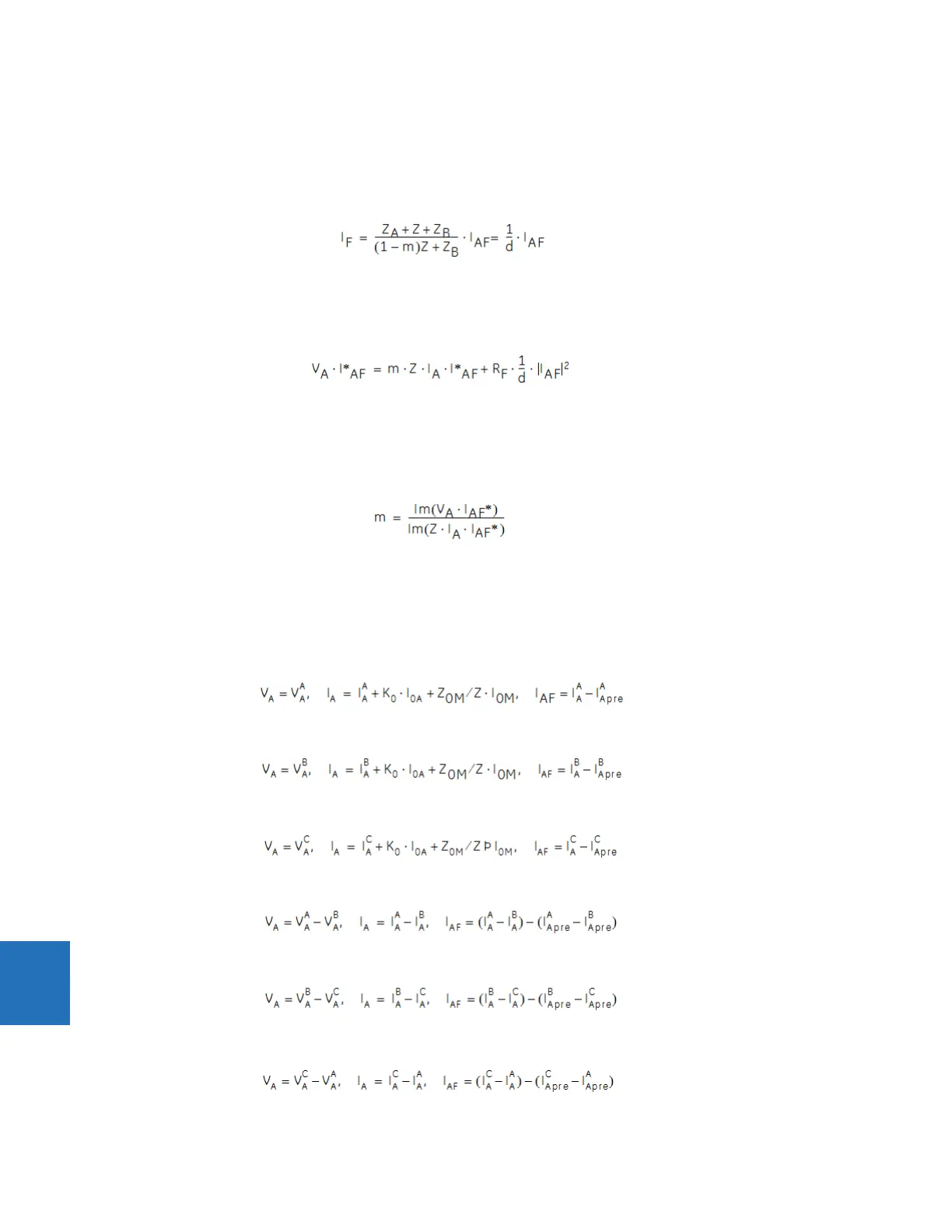
The fault network during a fault can be decomposed into a pre-fault and a pure-fault network. Therefore, the fault current
I
F
is calculated as follows by using the current division rule in the pure-fault network.
Eq. 9-2
where
d is the current distribution factor, which is a complex value
Substituting the second equation into the first equation and multiplying both sides by the complex conjugate of IAF,
Eq. 9-3
where
* denotes complex conjugate
Assuming the system is homogeneous, d is then a real number. The fault resistance does not have any imaginary part. The
preceding equation solved for the unknown m yields the following fault location algorithm:
Eq. 9-4
where
Im( ) stands for the imaginary part of a complex number
Depending on the fault type, appropriate voltage and current signals are selected from the phase quantities before
applying the preceding equation (the superscripts denote phases, the subscripts denote stations).
For AG faults:
Eq. 9-5
For BG faults:
Eq. 9-6
For CG faults:
Eq. 9-7
For AB and ABG faults:
Eq. 9-8
For BC and BCG faults:
Eq. 9-9
For CA and CAG faults:
Eq. 9-10

 Loading...


