3.3.7 Connecting interface devices
The UPS is equipped with two interface ports: a DB9 communication port and an SNMP card slot
(see section 3.3.8). Prepare the included serial communication cable (for DB9 communication port
connection) or the network cable (for SNMP communication connection) as follows:
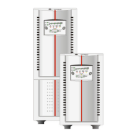
1. Choose from the 2 provided ferrite beads the smaller
one for serial communication and the bigger one for
SNMP communication.
2. Place the cable part that is close to the UPS connector
inside the ferrite bead. For SNMP communication twist it
once around the ferrite and place the second winding
also inside the ferrite bead (fig 3.3.7.a / 3.3.7.b).
3. Close the ferrite bead such that the cable remains
inside it (fig. 3.3.7.a / 3.3.7.b).
fig. 3.3.7.a
fig. 3.3.7.b
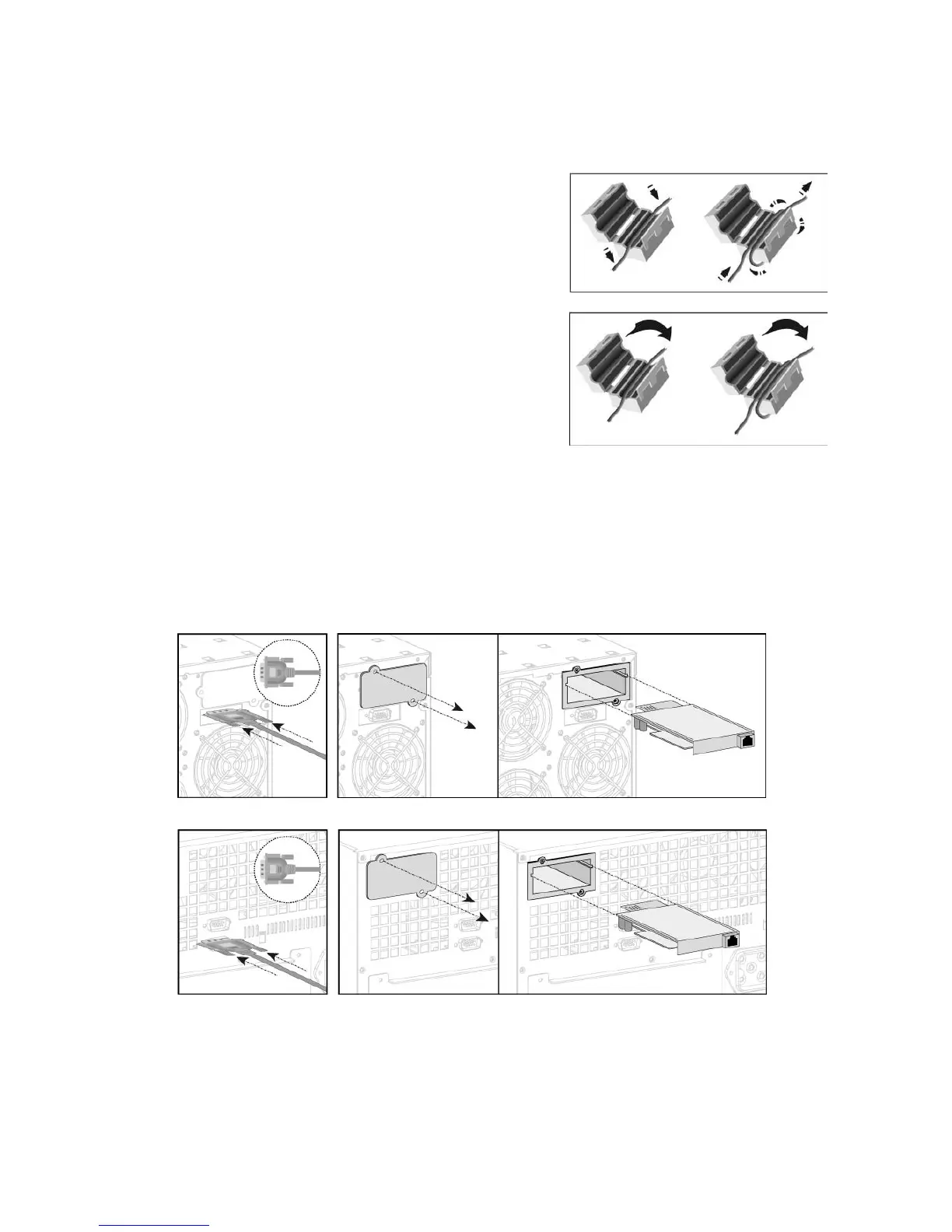
You can now connect the DB9 port to a computer by connecting the previously prepared serial cable
(fig. 3.3.7.c / 3.3.7.d). Additional signals can be read from the serial connector. See section 5.1 for more
information.
Open the SNMP slot by removing the two screws and the cover, then pull in the easy installation SNMP
Card and connect previously prepared network cable (fig. 3.3.7.e / 3.3.7.f). See section 5.2 for more
information.
fig. 3.3.7.d fig. 3.3.7.e
fig. 3.3.7.f fig. 3.3.7.g
5/6 kVA
5/6 kVA
8/10 kVA
8/10 kVA
modifications reserved 16 User manual GT Series 5/6/8/10 kVA UPS 1.0 (US)
 Loading...