50
L. REPLACEMENT PART LIST AND
PROCEDURES
Replacement Procedures
A. SYSTEM REPLACEMENT
A system may require replacement for one of three possible
reasons. The need for a system to be replaced must
be recommended and conrmed by a qualied service
technician. Possible reasons for replacement include:
1. The system (during commissioning or annual
maintenance) fails the integrity test.
2. The TMP result during annual maintenance after the
membrane cleaning is too high (greater than 20 psi TMP)
indicating there is too much fouling of the membrane
and the household water ow rate is too low. The water
quality entering the system will greatly inuence how fast
the system will foul.
3. The system is damaged on delivery and is not suitable
for installation.
Replacement instructions for UFC 211 and UF 211 series:
1. Close the inlet and bypass valves.
2. Depressurize the system by turning on a tap until no
water ows out from the tap.
3. Drain the system by activating a manual ush sequence.
Refer to the instructions in the Setting the Controller
section for how to perform a manual ush sequence.
4. Turn o the tap and close the outlet valve.
5. Unplug the controller.
6. Disconnect the drain solenoid valve cable and the inlet
solenoid valve cable (if applicable) at the controller Refer
to Figure 14.
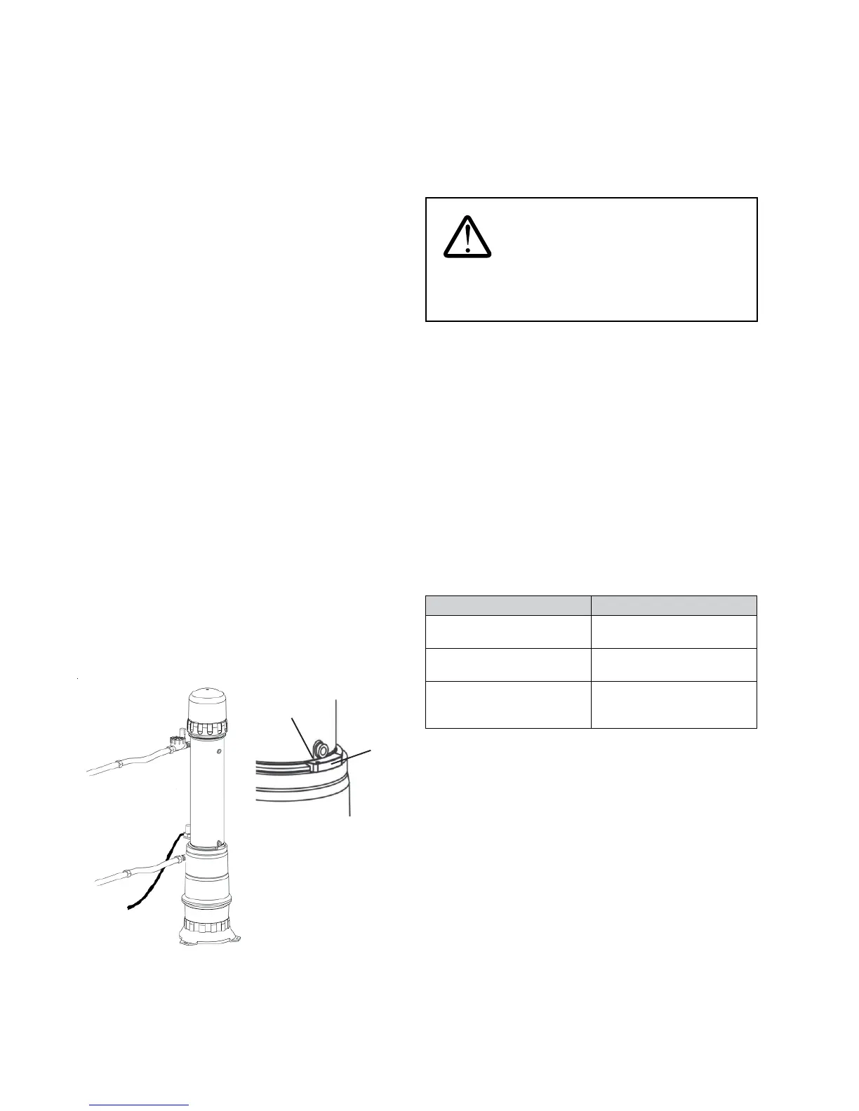
Follow steps 7 to 16 for vertical systems:
Locking
Clip
Locking
Clip
screw
Outlet
pipe
assembly
Inlet pipe
assembly
Backpulse
Tank
System
Casing
System
Cap
Drain line
assembly
Figure 83
7. Remove the air relief valve, the inlet pipe assembly, and
the drain line assemblies from the system. Removal of the
inlet pipe assembly may require disconnecting the inlet
line at multiple places.
8. Remove the inlet, drain, and air relief valve plugs from the
new system and insert those plugs into equivalent ports
of the old system.
WARNING: Some water may still
remain in the system. Plug the inlet, outlet, and drain
ports immediately once the pipe assemblies have been
removed.
9. Using the cap wrench, remove the system cap.
10. Remove the internal prelter from the system. Set the
internal prelter aside in a clean area for reuse.
11. Unscrew the locking clip screw and remove the locking clip.
12. Unscrew the system casing from the backpulse tank
using a strap wrench.
13. If under warranty, the old system must be completely
sealed, packaged and returned to the factory within
24 hours to avoid internal damage and allow a cause
analysis to be completed.
14. Label the box appropriately as in the table below. Call the
GE Homespring Consumer Products Customer Service for
shipping and handling details at
1-800-279-9404.
Label on System Box Use only if:
“INTEGRITY” + Homespring
Certied Technician Number
If the system has failed the
integrity test.
“FOULED” + Homespring
Certied Technician Number
If the system is fouled.
“DAMAGED” + Homespring
Certied Technician Number
If the system has been
damaged during transportation,
warehousing or installation steps.
15. Reattach the locking clip, air relief valve, inlet/outlet/drain
pipe assemblies, internal prelter, system cap, external
prelter (if applicable), and controller.
16. Reconnect the system to the house plumbing and the drain.
Follow COMMISSIONING to start up the system again.
 Loading...