16
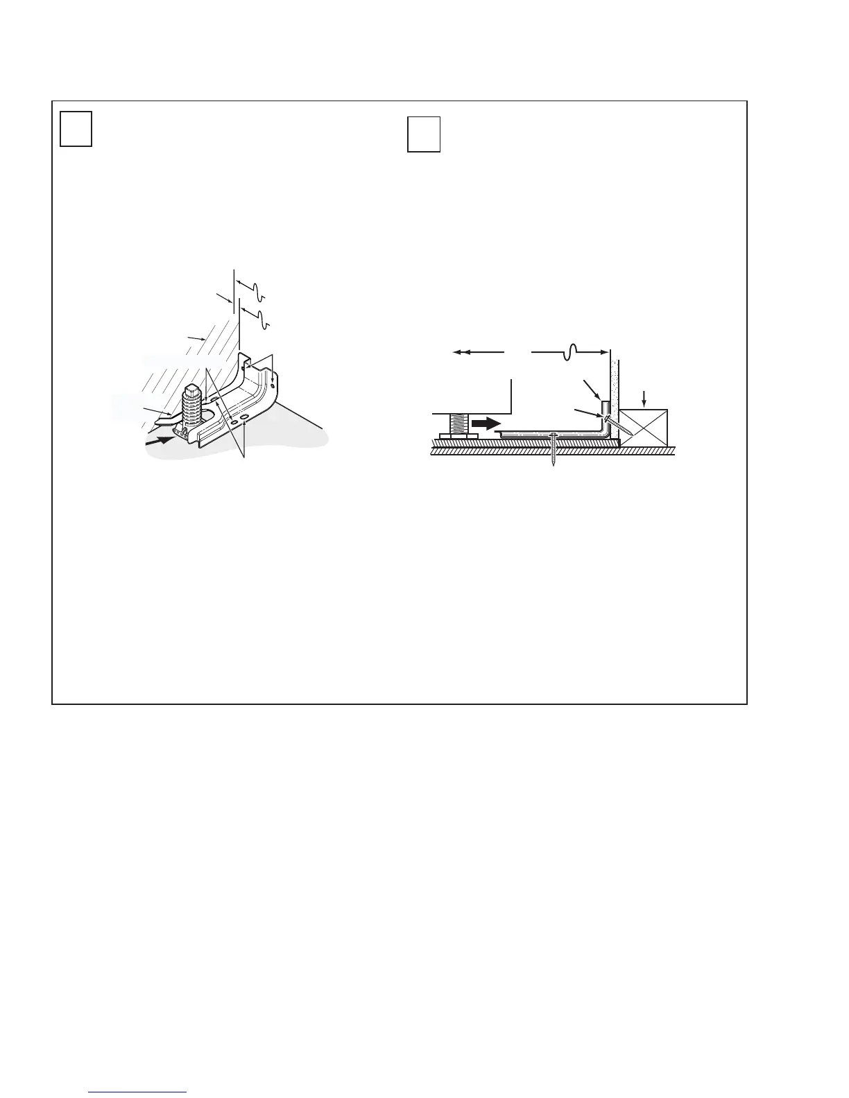
Anti-Tip Bracket Installation
Slide-In Range
a. Forconcreteinstallationyouwillneedtwo
1/4"x1-1/2"lagscrews,andtwosleeve
anchors.
b. Locatethecenterofthefourholesidentified
inFig.1asFloor-ConcreteandWall.Drill
therecommendedsizeholesineach.
c. Installthesleeveanchorsintothepredrilled
concreteholesandinstallthelagandwall
screwsthroughtheAnti-Tipbracket.Make
surethescrewsaresecurelytightened.
a. Locatethecentersofthefourholesidentified
inFig.1asFloor-WoodandWall.
b. Drilla1/8"pilotholethroughthepre-marked
areas.Notetheangleofthewallscrewin
Fig.2.
c. MounttheAnti-Tipbracketwiththefour
screwsprovided.
LocatingTheBracket
a. Decidewhetherthebracketwillbe
installedontherightorleftsideofrange
opening.
b. Placethebracketasshown inFig.1.
Fig.1
InstallingTheBracketinWood
orConcrete
D1
INSTALLATION
-WOODCONSTRUCTION
I
NSTALLATION
-CONCRETE CONSTRUCTION
D2
Fig.2
ATTACHMENT TO WALL
WALL
PLATE
BRACKET
SCREW MUST
ENTER WOOD
OR METAL
TO FRONT EDGE
OF
COUNTERTOP
25"
WALL
FLOOR-WOOD
REAR
LEVELING
LEG
ADJACENT CABINET
BRACKET
SIDE
FLOOR-CONCRETE
30"
Equal Space
Each Side
Larger Than 30" Opening
GEA01052
 Loading...