EasyManua.ls Logo

GE LOGIQ F8 Service Manual

GE LOGIQ F8
167 pages
To Next Page IconTo Next Page
To Previous Page IconTo Previous Page
Page #44 background image
GE LOGIQ F SERIES
DIRECTION 5446617-100, REVISION 10 BASIC SERVICE MANUAL
2 - 4 Section 2-2 - General Console Requirements
2-2-3 EMI Limitations
Ultrasound machines are susceptible to Electromagnetic Interference (EMI) from radio frequencies,
magnetic fields, and transient in the air wiring. They also generate EMI. The LOGIQ F Series complies
with limits as stated on the EMC label. However there is no guarantee that interface will not occur in a
particular installation.
Possible EMI sources should be identified before the unit is installed.
Electrical and electronic equipment may produce EMI unintentionally as the result of defect.
These sources include:
medical lasers,
scanners,
cauterizing guns,
•computers,
•monitors,
fans,
gel warmers,
microwave ovens,
light dimmers,
portable phones.
The presence of broadcast station or broadcast van may also cause interference. See for EMI
Prevention tips.
See Ta b l e 2-4 for EMI Prevention tips.
Table 2-4 EMI Prevention/abatement
EMI Rule Details
Be aware of RF sources
Keep the unit at least 5 meters or 15 feet away from other EMI sources. Special shielding
may be required to eliminate interference problems caused by high frequency, high
powered radio or video broadcast signals.
Ground the unit
Poor grounding is the most likely reason a unit will have noisy images. Check grounding of
the power cord and power outlet.
Replace all screws, RF
gaskets, covers, cores
After you finish repairing or updating the system, replace all covers and tighten all screws.
Any cable with an external connection requires a magnet wrap at each end. Install the
shield over the front of card cage. Loose or missing covers or RF gaskets allow radio
frequencies to interface with the ultrasound signals.
Replace broken RF gaskets
If more than 20% or a pair of fingers on the RF gaskets are broken, replace the gaskets.
Do not turn on the unit until any loose metallic part is removed.
Do not place labels where RF
gaskets touch metal
Never place a label where RF gaskets meet the unit. Otherwise, the gap created will permit
RF leakage. Or, if a label has been found in such a position, move the label.
Use GE specified harnesses
and peripherals
The interconnect cables are grounded and require ferrite beads and other shielding. Also,
cable length, material, and routing are all important; do not change from what is specified.
Take care with cellular phones Cellular phones may transmit a 5 V/m signal; that could cause image artifacts.
Properly dress peripheral
cables
Do not allow cables to lie across the top of the card cage or hang out of the peripheral bays.
Loop the excess length for peripheral cables inside the peripheral bays. Attach the monitor
cables to the frame.

Table of Contents

Question and Answer IconNeed help?

Do you have a question about the GE LOGIQ F8 and is the answer not in the manual?
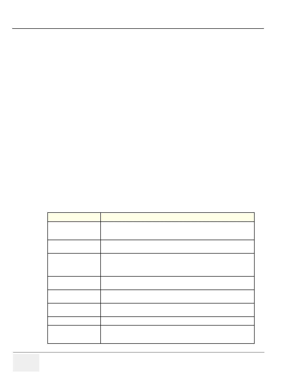
GE LOGIQ F8 Specifications

General IconGeneral
TypeUltrasound System
Probe Ports3 active probe ports
Probe Connectors3
PortabilityPortable
Operating Temperature10°C to 40°C
Relative Humidity30% to 85% (non-condensing)
Power Requirements100-240 V AC, 50/60 Hz
Imaging ModesColor Doppler, Power Doppler
ApplicationsAbdominal, Vascular, Cardiac, Musculoskeletal, Small Parts
Frequency Range2.0 MHz - 18.0 MHz (dependent on transducer)
Storage Temperature-20°C to 60°C

Summary

Introduction

Overview

Provides an overview of Chapter 1 and the manual's purpose.

Important Conventions

Explains book conventions, hazard icons, and safety messages.

Safety Considerations

Details human, mechanical, and electrical safety precautions.

EMC, EMI, and ESD

Discusses electromagnetic compatibility, interference, and static discharge prevention.

Lockout/Tagout (LOTO) requirements

Outlines procedures for applying Lockout/Tagout for service.

Customer Assistance

Provides contact information for support and troubleshooting.

Site Preparations

Overview

Introduces site preparation requirements for installation.

General Console Requirements

Covers environmental and electrical requirements for the console.

Facility Needs

Details purchaser responsibilities and required facility features.

System Setup

Overview

Outlines information needed for unit installation and setup procedures.

Setup Reminders

Provides reminders and average installation times.

Receiving and Unpacking the Equipment

Details procedures for receiving and unpacking the system.

Preparing for Installation

Covers verification, inspection, and EMI protection before installation.

Completing the Installation

Guides through powering on/off and connecting probes.

System Configuration

Details system specifications, optional peripherals, and connector panels.

Software/Option Configuration

Refers to the User Manual for software and option configuration.

Connectivity Installation Worksheet

Provides a worksheet for network connectivity setup.

Loading Base Image Software

Refers to procedures for loading base image software.

Software Version check out

Explains how to check system software version.

Paperwork

Covers documentation and user manual checks.

Functional Checks

Overview

Introduces procedures for checking system functions and diagnostics.

Required Equipment

Lists equipment needed for functional tests.

General Procedure

Details general procedures like power on/off, date/time check, and mode controls.

Components and Functions (Theory)

Overview

Explains system concepts, component arrangement, and subsystem functions.

Block Diagram

Presents system and software block diagrams.

Common Service Platform

Describes the common software modules for service.

Service Adjustments

Overview

Introduces scanner testing and adjustment procedures.

Monitor Adjustments

Provides procedures for adjusting monitor brightness and light.

Diagnostics/Troubleshooting

Overview

Details tools and software for maintaining image quality and system operation.

Gathering Trouble Data

Explains how to capture trouble images and system data for analysis.

Screen Captures

Guides on capturing screen images and setting up print keys.

Common Diagnostics

Covers utilities like disruptive mode and system shutdown.

Network Configuration

Details procedures for connecting the system to a network.

Replacement Procedures

Overview

Introduces procedures for replacing modules and subsystems.

DISASSEMBLY/RE-ASSEMBLY

Provides warnings and cautions for disassembly.

Renewal Parts

Overview

Provides an overview of renewal parts for the LOGIQ F Series.

List of Abbreviations

Lists abbreviations used in the renewal parts section.

Care & Maintenance

Overview

Discusses periodic maintenance and the purpose of care.

Why do Maintenance

Explains the importance of keeping records and quality assurance.

Maintenance Task Schedule

Outlines the recommended customer care and maintenance schedule.

Tools Required

Lists standard GE tool kits and special tools for maintenance.

When There's Too Much Leakage Current...

Provides troubleshooting steps for leakage current failures.

Related product manuals