OPM_LPS_31E_8K0_20K_1GB_V010.doc 15/40 Operating Manual LP 31 / 8-10-15-20 kVA
4. OPERATION
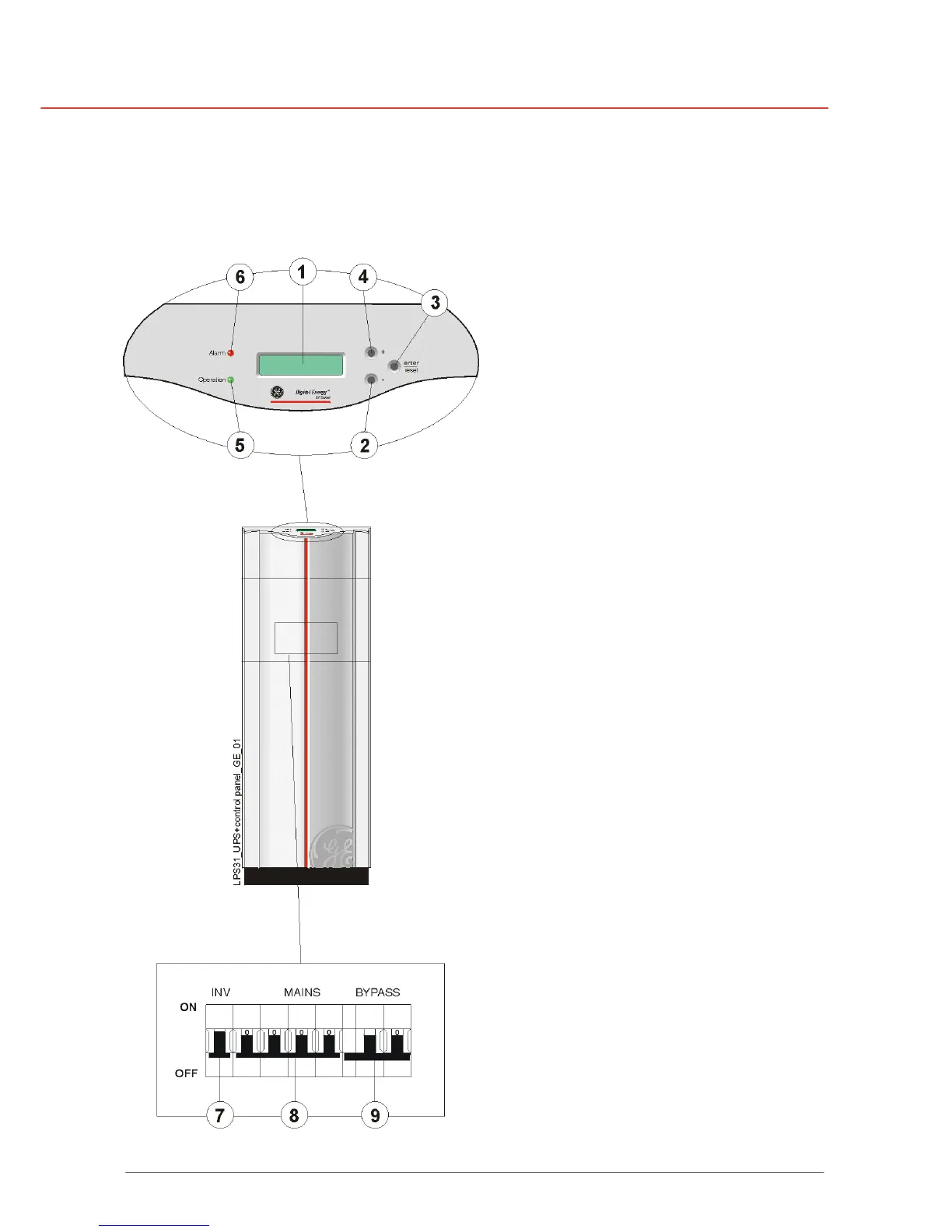
4.1 DESCRIPTION OF FRONT AND REAR PANEL
Figure 5 - Front panel
1 LCD screen
2x16 characters, shows UPS system
data, status messages, settings.
2 - 4 Push-buttons
With the button keypads “-” (2) and “+”
(4) you can scroll through the several
screens, with keypad “reset/enter” (3) a
selection is confirmed.
Keypad activity is accompanied by a
short beep.
If there is no keypad activity during 20
seconds the LCD screen will return to
the default screen (except for the service
screens, see chapter 4.3.3).
5 LED “operation”
Normal operation.
6 LED “alarm”
Indicates an alarm situation,
accompanied by alarm message(s) on
the display and a sounding buzzer.
See chapter 4.3.2 for more information
7 Inverter ON/OFF switch
Turn ON/OFF the inverter.
ATTENTION!
This switch does not switch OFF the
bypass.
When (7) is switched into OFF position,
the bypass voltage will be supplied to
the load.
8 Line fuse (MCB)
Protection fuse for mains input and
battery charger.
9 Bypass fuse (MCB)
Protection fuse in case of overload or
short circuit in the UPS load.

 Loading...


