ALIGNMENT AND TROUBLESHOOTING PROCEDURES
LBI-38438A 15
5.1.7 Audio Output Level Adjustment Procedure
STEP
METERING
POINT
TUNING
CONTROL
METER
READING PROCEDURE
1 J701-1 RV601 See
Procedure
Set the signal generator to the receiver
frequency with ±3 kHz deviation and 1 kHz
modulation. Set the RF signal level to 1000
microvolts. Move P551 from J551-1, 2 to J551-
2, 3 on the Transmitter/Receiver Board.
Connect RF signal generator to J1.
Terminate J701-1, 6 with a 4 ohm, 6-watt
resistor, connect the audio level meter and the
distortion analyzer input across the resistor. Set
the volume to the maximum point. Press DOWN
button two times. Adjust RV601 for 4-watt
output (4 Vrms, using the distortion analyzer as
Volt Meter).
Return P551 to J551-1, 2.
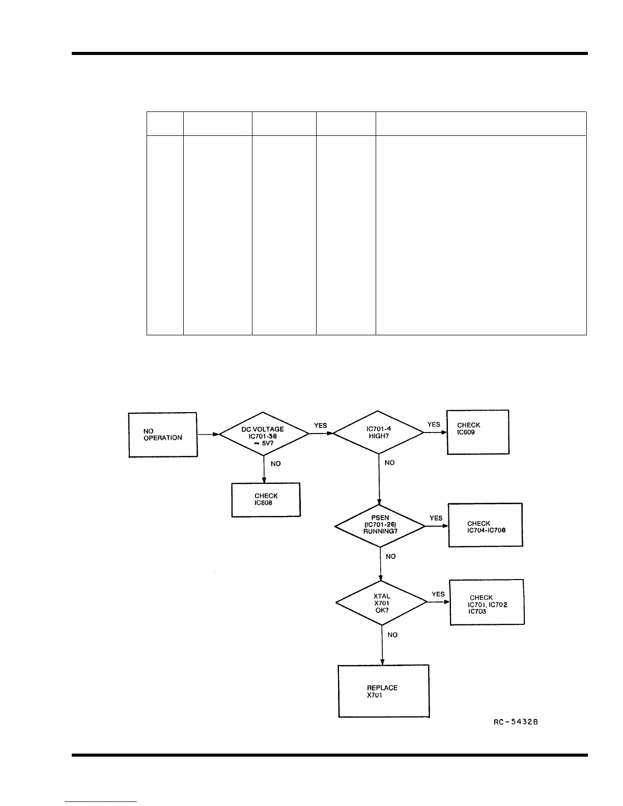
Control Logic Troubleshooting
 Loading...