12 469 MOTOR MANAGEMENT RELAY – QUICK REFERENCE GUIDE
QUICK REFERENCE GUIDE
5 Typical application setup
The relay leaves the factory with setpoints programmed to default values, and it is these
values that are shown in all the setpoint message illustrations. Many of these factory
default values can be left unchanged.
At a minimum, the
S2 SYSTEM SETUP setpoints must be entered for the system to function
correctly. To safeguard against the installation of a relay whose setpoints have not been
entered, the “Warning, 469 Not Programmed” self-test warning is displayed. In addition,
the 5 Block Start relay will be energized, and the “469 In Service” LED will be off. Once the
relay programming is complete, the relay should be in the Service state.
For a typical example on how to set the 469 for motor protection, refer to the “Application
Example” on page 42. In addition to providing typical wiring diagrams, the example covers
the procedure to set the following features of the 469:
5.1 System setup for phase, neutral and ground CTs
• CT primary ratings
• CT secondary ratings
• CT turn ratio
5.2 System setup for VTs
• VT primary ratings
• VT secondary ratings
• VT turn ratio
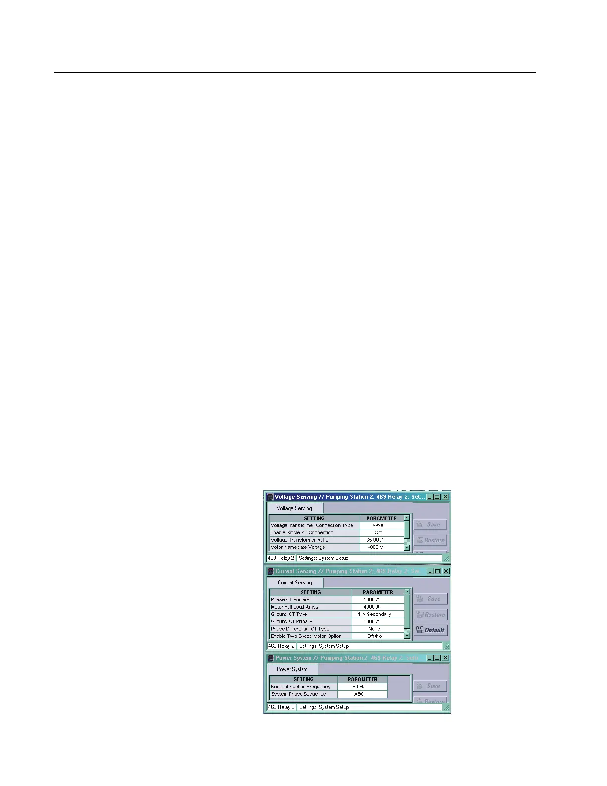
Setpoints can be accessed with the EnerVista 469 setup software. To access the setpoints
listed above, select the Setpoints > System Setup > Current Sensing, Setpoints > System
Setup > Voltage Sensing, and Setpoints > System Setup > Power System menu items.
 Loading...


