QUICK REFERENCE GUIDE
469 MOTOR MANAGEMENT RELAY – QUICK REFERENCE GUIDE 31
11 Advanced EnerVista 469 Setup features
11.1 Triggered events
While the interface is in either on-line or off-line mode, data generated by triggered
specified parameters can be viewed and analyzed via one of the following:
• Event Recorder: The event recorder captures contextual data associated with the last
256 events, listed in chronological order from most recent to the oldest.
• Oscillography: The oscillography waveform traces provide a visual display of power
system data captured during specific triggered events.
11.2 Waveform capture (trace memory)
The EnerVista 469 Setup software can be used to capture waveforms (or view trace
memory) from the 469 relay at the instance of a trip. A maximum of 128 cycles can be
captured and the trigger point can be adjusted to anywhere within the set cycles. A
maximum of 16 traces can be buffered (stored) with the buffer/cycle trade-off.
The following waveforms can be captured:
• Phase A, B, and C currents (I
a
, I
b
, and I
c
)
• Differential A, B, and C currents (I
diffa
, I
diffb
, and I
diffc
)
• Ground currents (I
g
)
• Phase A-N, B-N, and C-N voltages (V
an
, V
bn
, and V
cn
) for wye connections
• Phase A-B and B-C (V
ab
and V
bc
) for open-delta connections
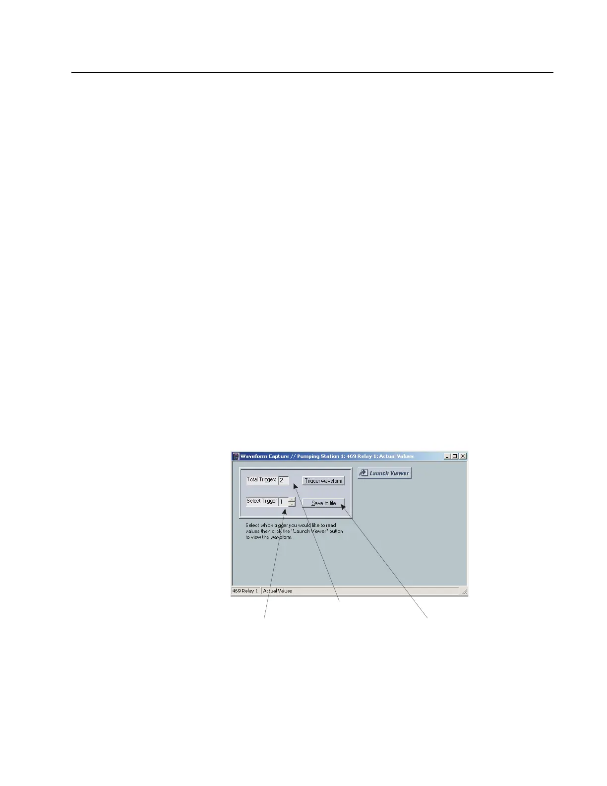
1. With EnerVista 469 Setup running and communications established, select the Actual
> Waveform Capture menu item to open the waveform capture setup window:
2. Click on Trigger Waveform to trigger a waveform capture.
The waveform file numbering starts with the number zero in the 469; therefore, the
maximum trigger number will always be one less then the total number triggers
available.
Number of available files
Files to be saved or viewed
Save waveform to a file
 Loading...


