GE_UPS_OPM_SGS_ISG_10K_40K_0US_V070.docx
Installation Guide SG Series 10-20-30-40 UL S
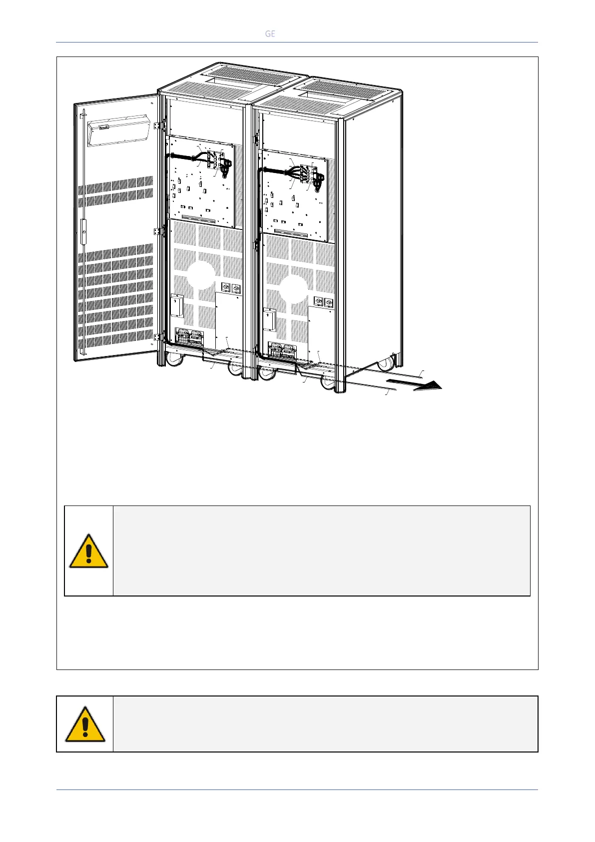
Fig. 3.9.3-3 Control Bus cable routing and connection
Control bus cables routing
Place and fix the cables JA-1/2/3/4/5/6/7 and JB-1/2/3/4/5/6/7 with the appropriate clamps inside
the UPS cabinets in the position shown in the drawing Fig 3.9.3-1.
Pay attention to the fact, that routing of cables shall allow the removal of the protection covers “A”.
NOTE !
Pay attention when cabling and routing the bus cables JA and JB inside the UPS
cabinet.
In case one unit should be removed from the parallel system, the bus cables JA and
JB must be removed from the cabinet without disconnecting them from the metal
plate where the sockets JA and JB are located.
For reliability reasons the cables JA-1/2/3/4/5/6/7 and JB-1/2/3/4/5/6/7 connecting the units should
be run in separated protected conduits (as indicated in Fig. 3.9.3-3) separated from the power
cables.
It is important that the cable JA must be the same length as cable JB.
WARNING !
Connection and commissioning of an additional UPS to an existing parallel system,
must be performed by a GE SERVICE ENGINEER from of your Service Center.
SGT5000_030-040_RPA control bus cable_02US
Next parallel
unit 3, 4, 5, 6, 7, 8
JB2
JA2
UPS 1
JA1
JB1
JA1
JB1
JB
JA
JB1
JB2
JB
JA
JA2
JA1
JA2
UPS 2
Q2
Q1
OFF
ON
OFF
ON
JB2
A
A
ON
OFF
Q1
Q2
ON
OFF
 Loading...