GE_UPS_OPM_SGS_ISG_10K_40K_0US_V070.docx
Installation Guide SG Series 10-20-30-40 UL S
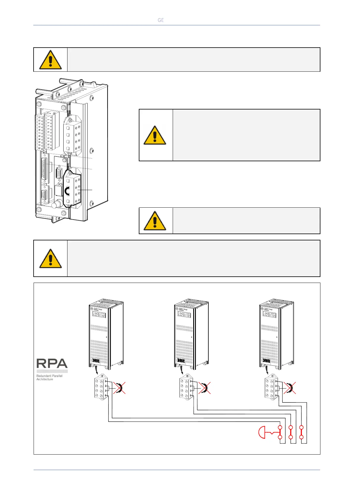
4.1.7 “EPO - Emergency Power Off” command connection
Be aware:
The reliability of the system depends on this contact NC (Normally Closed)!
Fig. 4.1.7-1 Terminals for connection EPO
An external Emergency switch (Normally Closed voltage-free
contact) can be connected on terminals XB / 1 - 4 or connector
J2 / 12 - 25 of the “P4 - Customer Interface”.
NOTE !
To enable this function, remove cable short-
circuiting XB / 2 - 3 on the Terminal XB and the
Jumper JP3 on “P4 - Customer Interface”, when
the cables have been already connected on XB
or J2.
When opened, this contact causes the immediate opening of the
Contactors K3, K4, K6, K7 and K8, as well as the shut-down of
Rectifier, Inverter and Static-Switch.
NOTE !
This procedure could imply a load shut-down.
NOTE !
In case of parallel Customer Interface the EPO contact must be connected to one “P4
- Customer Interface” only, but the bridge on X2 and jumper JP3 on the “P4 -
Customer Interface” must be removed on all other boards.
In a Parallel System a separate NC (Normally Closed) contact must be connected
individually to each unit.
Fig. 4.1.7-2 XB “EPO - Emergency Power Off” – RPA Parallel System connection schematics
4
1
3
2
3
2
1
SGT5000_100-150_Customer interface EPO_01
4
XB
J2
JP3
EPO
2
4
3
1
XB
XB 2-3
2
4
3
1
XB
XB 2-3
2
4
3
1
XB
XB 2-3
SGSU_010-040_UPS_EPO-RPA connection schematic_GE_01
 Loading...