GE_UPS_USM_TLE_SUL_M16_M50_2bU_V010.docx
User Manual TLE Series 160 - 500 UL S2B
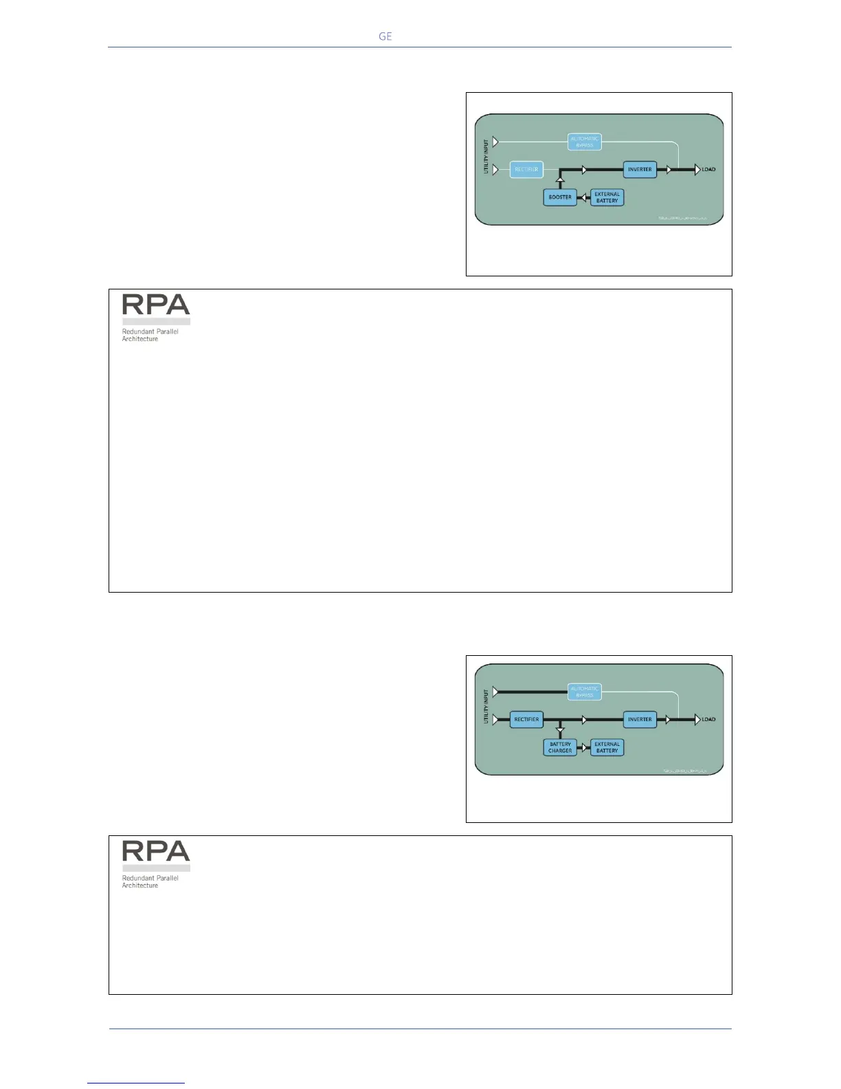
4.2.3 Utility Failure Operation
When the Utility is no longer within acceptable tolerances,
the
Battery will provide the DC power to the Inverter.
Inverter will maintain continuous AC power to the
until the Battery Voltage reaches the lower limit of
Inverter operation capability.
During the discharge, the
LCD screen shows the estimated
Battery can support the critical Load.
Battery discharge, the "stop operation"
shut-down imminent) warns the operator that the
is almost discharged and the UPS is about to shut
Fig. 4.2.3-1 Block diagram Utility Failure operation
In case of RPA Parallel System
With a Parallel System for power capacity (see Section 4.3)
• With the Bypass Utility power available, a “Battery low” warning on any unit will cause the Load
to be transferred to Utility (after a selectable time delay).
• With Bypass Utility power not available, a “Battery low” warning on any unit will start the “stop
operation” timer (adjustable).
The Load will shut down at the end of the “stop operation” time period.
With a Parallel System for redundancy (see Section 4.3)
• When a Battery low warning occurs on a unit not necessary to support the present Load, this unit
will shut down after a timeout period (selectable).
The Load is shared between the other units.
• As the warning occurs on one unit necessary to support the present Load, the system starts the
"stop operation" timeout (selectable).
The Load will shut down at the end of the “stop operation” time period.
4.2.4 Utility Recovery Operation
As soon as the AC input power recovers, the Rectifier will
start automatically
, supplying DC power to the Inverter
was previously shut down due to low
Battery
, the Load will be initially powered by Utility
Battery is sufficiently recharged to ensure a
minimum time of operation with the present
will start automatically and the Load
will be
transferred back to the Inverter.
Fig. 4.2.4-1 Block diagram Utility recovery operation
In case of RPA Parallel System
When the AC input power recovers, the Rectifiers will start-up sequentially, according to their
number in the Parallel System. This minimizes the initial inrush current.
The Inverters will start-up automatically, but only when the Battery has been sufficiently recharged
for a minimum runtime with the present Load.
When enough Inverters to supply the Load have been restarted, the Load will be transferred from
the Automatic Bypass back to the Inverter output.
 Loading...