GE_UPS_USM_TLE_SUL_M16_M50_2bU_V010.docx
User Manual TLE Series 160 - 500 UL S2B
2. Close “Q1 - UPS Output switch” (Pos. I).
•
Rectifier starts automatically.
LED 1 (Rectifier) blinking, indicates Soft-start.
• At the end of Rectifier Soft-start the LED 1 (Rectifier) remains lit.
NOTE !
Ensure the LED 1 (Rectifier) is lit before carrying out this procedure.
It indicates that the DC-link 1 and DC-link 2 has reached 400Vdc (see screen MEASURES /
Rectifier)!
Before performing the next procedure (4) make sure that the
(Booster/Battery charger) is lit.
Attention: check the right DC polarities on both side of the switch/fuse holder!
3. Connect the Battery to the UPS by closing the “External Battery Protections” and close, if
present, the “CB3 – External Battery switch” (option).
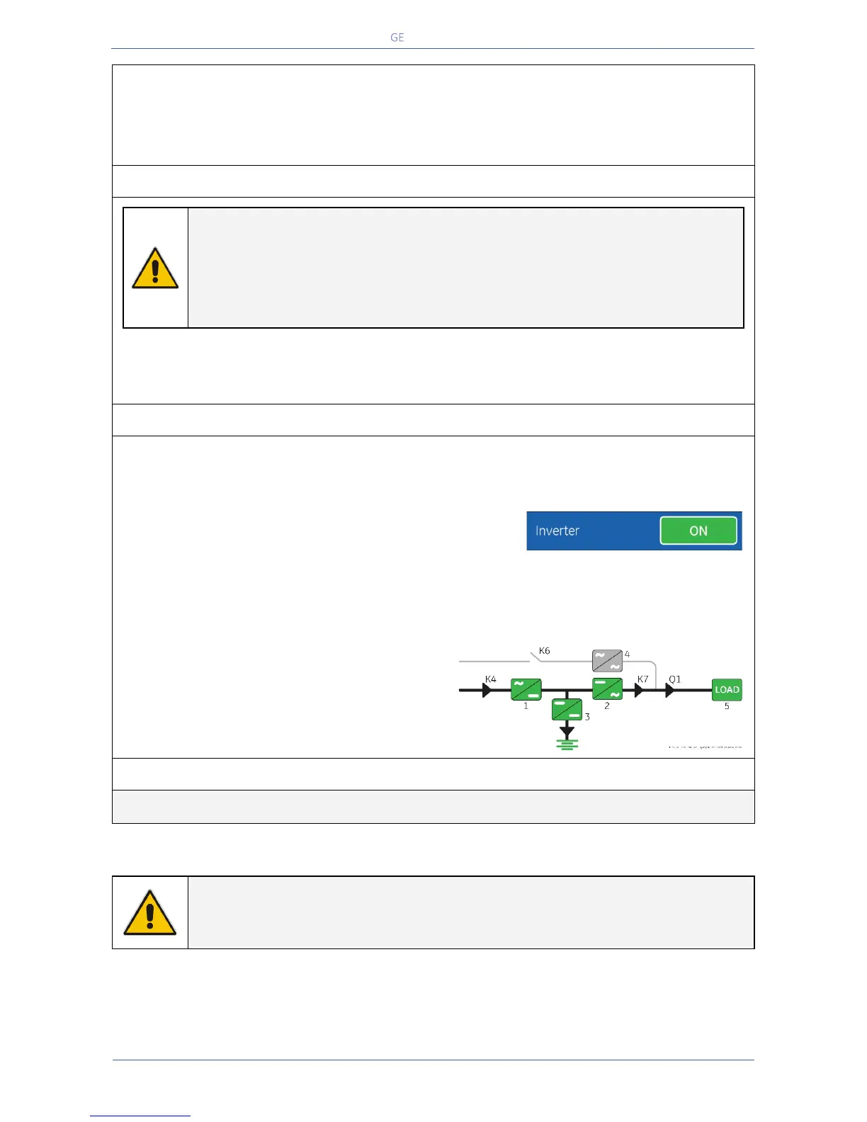
4. Insert the Inverter performing the command “Inverter ON".
Before performing this procedure make sure that the LED 1 (Rectifier) and LED 3 (Booster/Battery
charger) are lit.
Perform the “Inverter ON” command from the screen:
Commands 1 / Inverter / ON.
• Soft-start of Inverter indicated with blinking LED 2 (Inverter).
• At the end of Soft-start the LED 2 (Inverter) remains lit.
• Load is now supplied from Inverter.
• LED ALARM turns Off and the LED LOAD PROTECTED must be lit.
The Synoptic Diagram must display the status
“LOAD SUPPLIED BY INVERTER”.
END OF PROCEDURE
NOTE !
The Battery must be charged for at least 10 hours, in order to ensure the full backup
runtime in case of a Utility Failure.
 Loading...