GE_UPS_USM_TLE_SUL_M16_M50_2bU_V010.docx
User Manual TLE Series 160 - 500 UL S2B
NOTE !
Ensure the LED 1 (Rectifier) is lit before carrying out this procedure.
It indicates that the DC-link 1 and DC-link 2 has reached 400Vdc (see screen MEASURES
/ Rectifier)!
Before performing the next procedure (4) make sure that the LED 3
(Booster/Battery charger) is lit.
3. Connect the Battery on the Unit to reconnect by closing the “External Battery Protections” and
close, if present, the “CB3 – External Battery switch” (option).
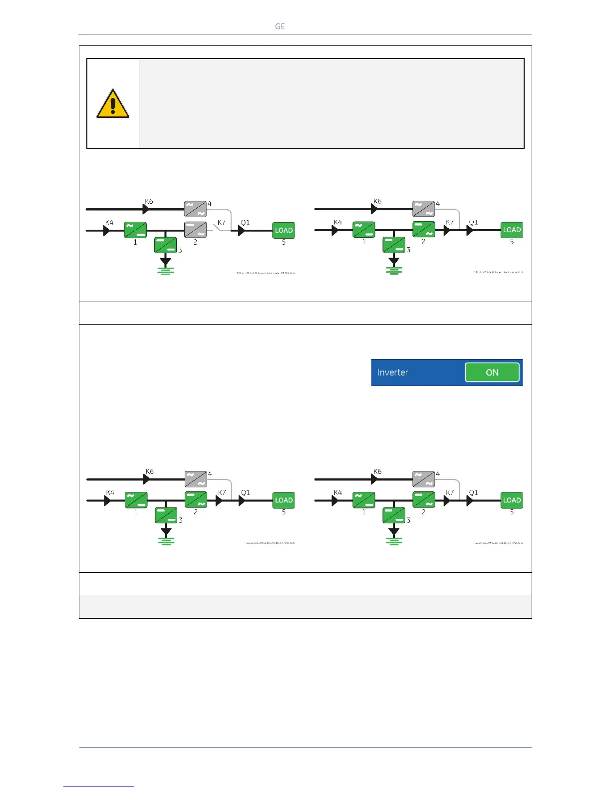
Synoptic diagram of the unit to reconnect
Synoptic diagram of other units
4. Insert the Inverter performing the command "Inverter ON” on the Unit to reconnect.
Perform the “Inverter ON” command from the screen:
Commands 1 / Inverter / ON.
• After Soft-start of the Inverter, the Inverter connects automatically to the other Units of the Parallel
System.
• LED ALARM turns Off and the LED LOAD PROTECTED must be lit.
The Synoptic Diagram, on all UPS units, must display the status “LOAD SUPPLIED BY INVERTER”.
Synoptic diagram of the unit to reconnect
Synoptic diagram of other units
 Loading...