Operating Instructions
6 VeriDri™ User’s Manual
4 Making the Wiring Connections
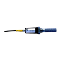
You must wire the transmitter using the factory-supplied cable, which is
available in a variety of lengths.
Note: If you need to lengthen cables, refer to Table 1 below to splice an
extension onto the existing cable. Be sure to connect positive to
positive and negative to negative.
Use the following steps to wire the transmitter to your system:
1. Push the female connector end on the transmitter cable into the
mating male connector on the transmitter module. Make sure the
pins are properly aligned. Then, secure the connectors together by
sliding the metal sleeve on the cable over the connectors and
turning it clockwise until it is tight.
2. Using the flying leads at the other end of the transmitter cable,
connect the transmitter to your power supply and data acquisition
system (DAS), as shown in Figure 2 on page 7. Refer to Table 1
below for a description of the leads on the factory-supplied cable.
3. Trim any unused leads back to the outer cable jacket, to remove the
bare tinned wire and prevent accidental short circuits.
The VeriDri is now ready for operation.
Table 1: Cable Lead Descriptions
Lead Color* Connection Description
Blue (+) 7 to 28 VDC
Brown (−) 7 to 28 VDC
Shield Connect to ground, if desired
*The blue and brown leads also produce a current output
equivalent to 4 to 20 mA.

 Loading...