– 18 –
The main control board has harness connections at
locations J1, J5, and JP7, and a model selector plug
located at J14. When the control receives power, it
checks for the presence of the model selector plug.
If no plug is detected, all LEDs will fl ash. Pressing the
start button has no effect on control operation. All
LEDs will stop fl ashing once a plug is installed.
Note: The model selector plug must be transferred
when control board is replaced.
Main Control Board - Rear View
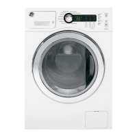
Note: The options selector has detents between
some of the settings. The washer will function if the
knob is inadvertently set at one of the unmarked
detents. Following a clockwise direction, all
unmarked detents have the same value as the
marked detent before it. The highlighted areas
below show an example of what settings would be
selected.
J5
JP7
J14 - Model Selector Plug
J1
To remove the control board assembly:
Disconnect power.1.
Place the control panel in the service position. 2.
(See Control Panel.)
Note: The knobs are NOT mounted to the controls
or switches. Each knob rests and rotates on a collar
imbedded in the control panel. The collar protects
the component from damage if something hits the
knob. A lockring on the back of the knob secures the
knob to the collar.
Remove the control, temperature, and options 3.
knobs by gently pulling each outward.
Disconnect wire harnesses J1, J5, and JP7 from 4.
the main control board.
Remove the two 1/4-in. hex-head screws from 5.
the main control board and the three 1/4-
in. hex-head screws and the brace from the
secondary board.
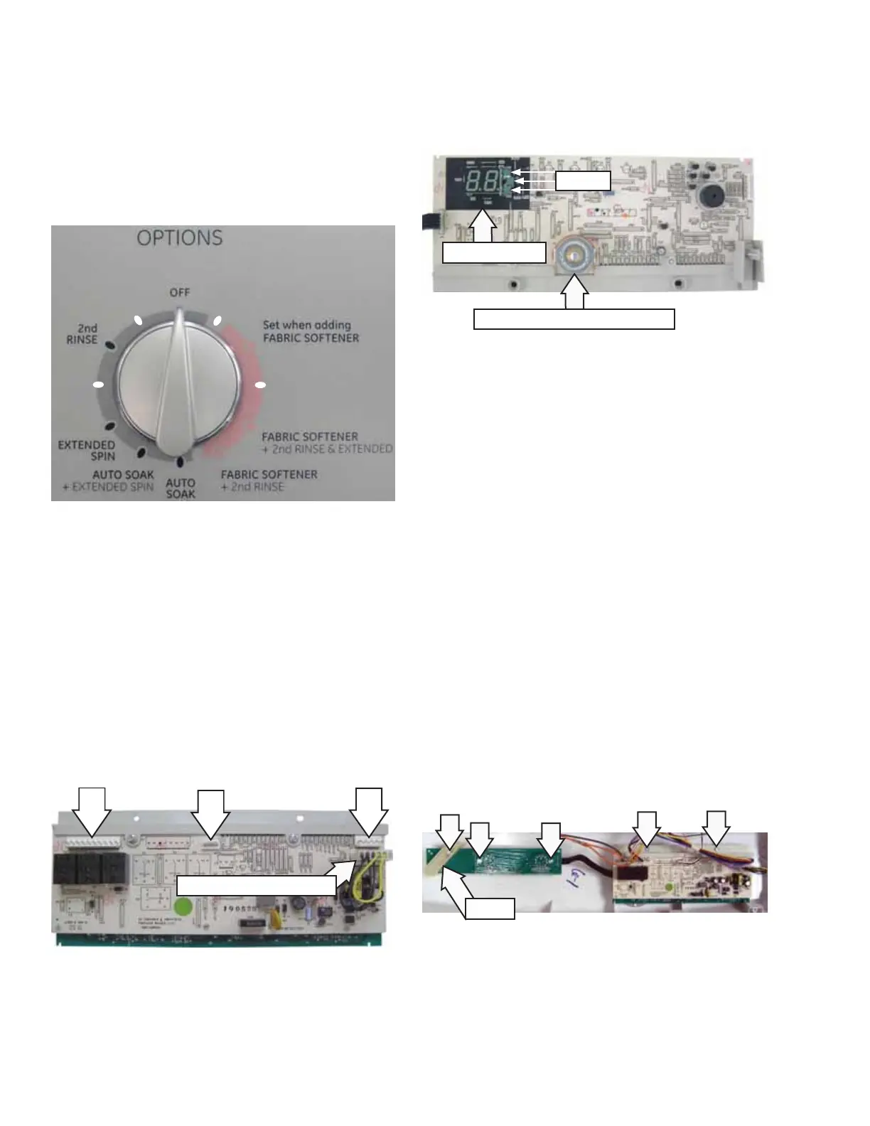
Main Control Board - Front View
Main Selector Rotary Switch
3 LEDS
2 Digit Display
Note: The LEDs in the 2 digit display can be as
much as 1/8-in. lower than the description on the
backsplash.
Brace
 Loading...