– 40 –
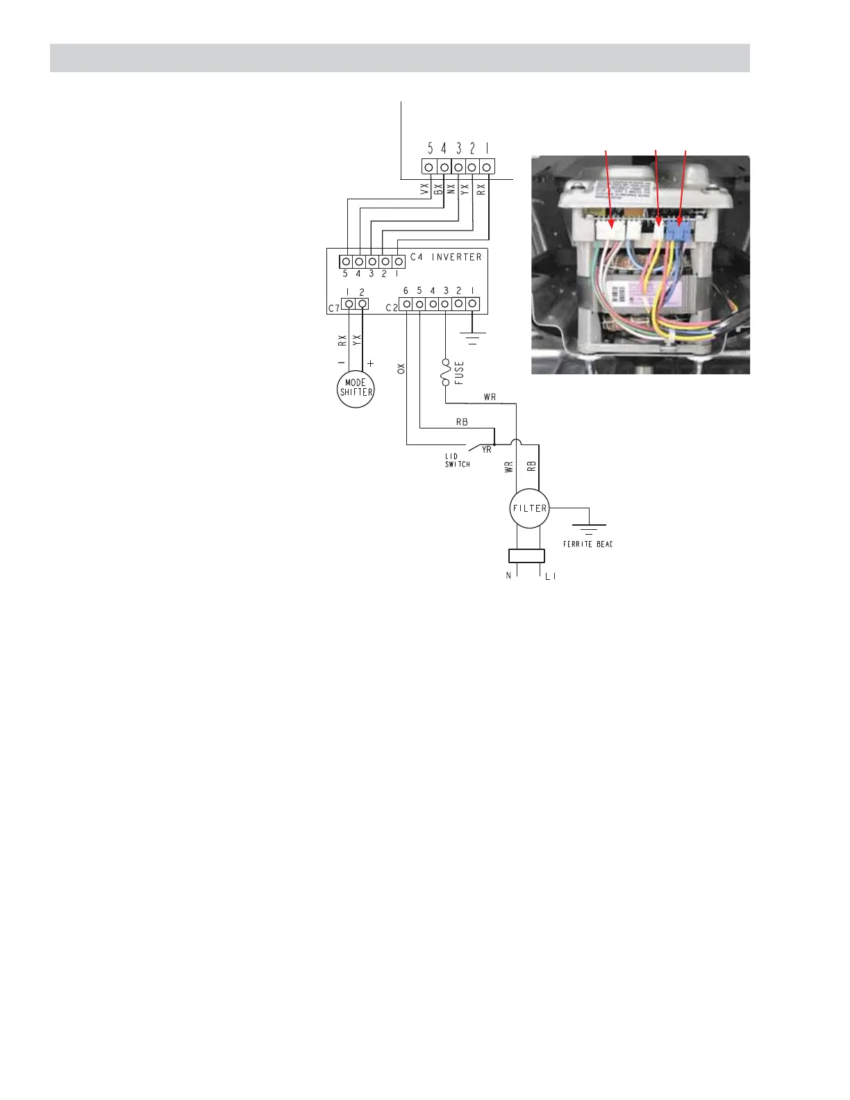
Inverter/Motor Test
Note: All electrical testing is done at
harness plugs.
Voltage readings:
C2 Pin 1 = Gnd
C2 Pin 3 = N
C2 Pin 5 to Pin 3 = 120 VAC
C2 Pin 6 to Pin 3 = 120 VAC with lid
switch closed
C7 Pin 1 to Pin 2 = 135 VDC**
C7 Pin 1 to Pin 2 = 30 VDC**
C4 Pin 5 to Pin 1 = 0 VDC*
C4 Pin 5 to Pin 2 = 0 VDC*
C4 Pin 5 to Pin 3 = 12 VDC*
C4 Pin 5 to Pin 4 = 12 VDC*
* Place washer in fi eld service mode spin
test (Knob Position 9). If 12 VDC is present
at specifi ed pins, main control is OK. If
motor runs in spin test, inverter, motor
and wiring harness are OK.
** 135 VDC is present for approximately
15 seconds at the beginning of the
agitate program. 30 VDC is present during
the remainder of the agitate cycle.
Caution: If the mode shifter coil is open,
C7 Pin 1 to Pin 2 can measure as high as
300 VDC.
MAIN CONTROL BOARD
Voltage readings in fi eld service mode agitate low test (Knob Position 6):
C4 Pin 5 to Pin 1 = 12 VDC
C4 Pin 5 to Pin 2 = 12 VDC
C4 Pin 5 to Pin 3 = 0 VDC
C4 Pin 5 to Pin 4 = 0 VDC
Voltage readings in fi eld service mode agitate high test (Knob Position 7):
C4 Pin 5 to Pin 1 = 12 VDC
C4 Pin 5 to Pin 2 = 0 VDC
C4 Pin 5 to Pin 3 = 12 VDC
C4 Pin 5 to Pin 4 = 0 VDC
 Loading...