– 17 –
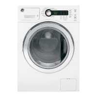
Rotate the top of the control panel forward 4.
approximately 1 inch and slide to the right to
unlock the 3 bottom locking tabs.
Lift the panel up and off the cover panel and rotate 5.
down.
Service Position
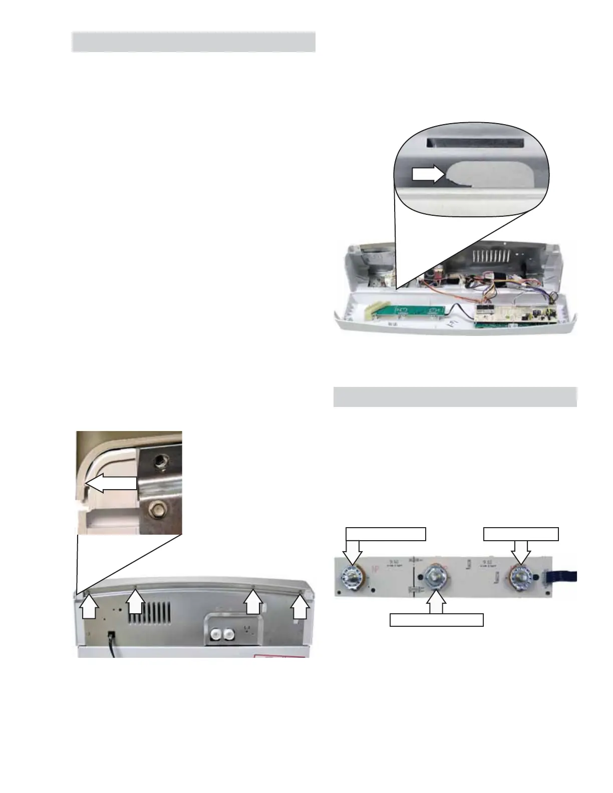
Control Board Assembly
The control board assembly is mounted on the
inside of the control panel. It is inserted in 3 panel
slots and held in place by 5 screws. It consists of
a secondary board permanently connected to the
main board with a ribbon. The secondary board
contains the water temperature control and the
options selector.
Options Selector
Load Size Switch
Temperature Selector
Unsnap
(Continued next page)
Tab
Control Panel
It is necessary to remove the control panel from the
backguard and place it in the service position to
access:
Control circuit board•
Water level switch•
Water valve•
AC line fi lter•
ATC Thermistor•
To place the control panel in the service position:
Caution: To prevent damage to the control panel,
place a protective pad on the cover/lid assembly.
Note: The control panel is attached to the washer
with four 1/4-in hex-head screws at the top and 3
tabs that engage 3 slots in the cover/lid assembly.
Disconnect power.1.
Remove the four 1/4-in. hex-head screws from 2.
the rear of the control panel.
Gently pull out each top rear corner to unsnap 3.
the control panel from the sides of the unit.
 Loading...