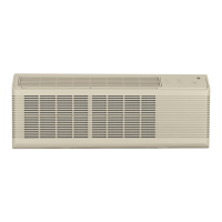
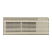
3100 SERIES
Auxiliary Control Panel
CLASS 2 REMOTE
Coc
e@Oe
80
me
BY
WGRC
E
FAN
uNIT
CYCLE
POWER
CONTROL
-1
m]
m
CYCLE CONT OFF ON NORMAL REMOTE
The CLASS 2 REMOTE and CDC terminals are
located behind a cover plate above the
auxiliay
controls. To remove the plate, remove and save
the screws that hold the plate to the unit.
IMPORTANT: After the wire connections are
completed, replace the plate to prevent damage
to
the unit or personal injuy.
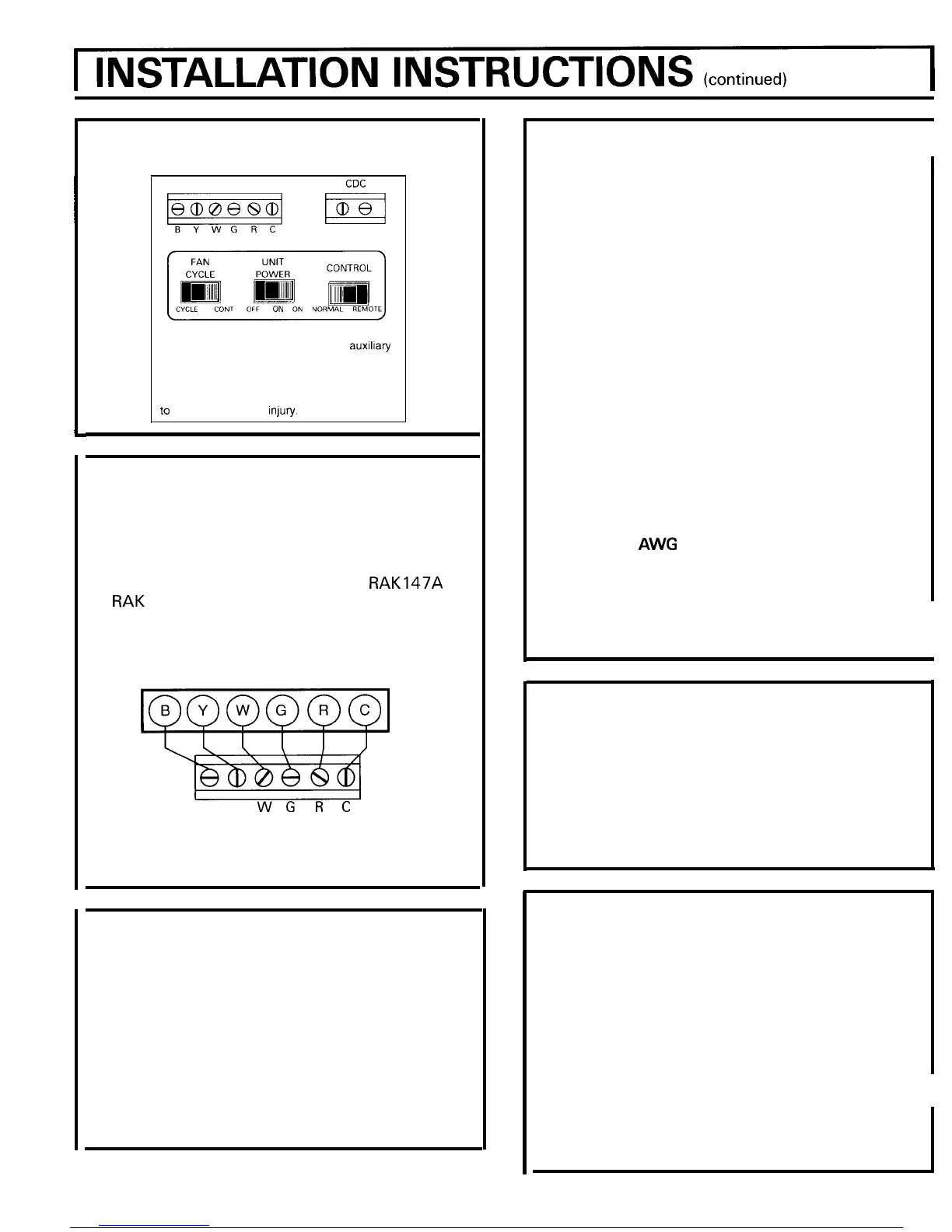
REMOTE CONTROL – 3100 SERIES
The unit may be controlled either by the unit
mounted controls or by changing the “CONTROL”
switch located behind the room cabinet to
“REMOTE” and connecting the unit to a 6 wire
Class 2 remote thermostat (GE Model
RAK147A
or RAK 152A or equivalent) the unit may be
converted to remote thermostat control.
2
STAGE HEAT
1 STAGE COOL
MANUAL THERMOSTAT
BY
WGRC
CLASS 2 REMOTE
LOW VOLTAGE
TERMINAL ON ZONELINE
FREEZE SENTINEL
The unit is equipped with a sensor that
automatically turns on the resistance heater and
fan if the room temperature, as sensed at the unit,
drops to approximately 40° F. and will shut the
heater off when the temperature reaches about
520 F. The Freeze Sentinel system helps prevent
damage due to sub-freezing temperatures and will
operate regardless of the mode setting of the unit.
Freeze Sentinel is active as long as power to the
unit has not been interrupted.
10
CENTRAL DESK CONTROL
The unit may be connected to a switch at the front
desk. When the switch is OPEN the unit is operable.
When the switch is CLOSED, the unit is made
inoperable. Connect the wires from the central
control system to the “CDC” terminals located on
the panel behind the room cabinet. Follow the
recommended wire sizing in the table below. Two
wires must be used from each CDC switch to each
individual unit. Do
not use a common buss in the
CDC wiring. A 24 volt transformer is contained
within the unit and no external voltage should be
applied to the unit through the CDC terminals. These
terminals may also be used as an interface for other
systems used to control the unit, such as infrared
detectors, key-activated systems, etc. The Freeze
Sentinel remains in an active mode to help protect
against low temperature damage even though the
unit may be “OFF” at the central control location.
Recommended
Wire Size for Central Desk
Control Installation
Wire Size #
AWG
Maximum Allowable Length
#24
400 ft.
#22
600 ft.
#20
900 ft.
#18
1500 ft.
#16
2000 ft.
I
FAN CYCLE SWITCH
This switch is set at CONT at the factory to provide
continuous fan operation in cool or heat modes.
Leaving the switch in the CONT setting allows
continuous circulation of room air and will result in a
more uniform temperature throughout the room.
Setting the switch at CYCLE will cause the fan to cycle
on and off with the compressor or resistance heater.
UNITPOWER SWITCH
This switch controls power to the cool, heat and fan
modes. It is set in the ON position at the factory to
allow the air conditioner to operate in these modes.
If this switch is set in the OFF position the air
conditioner will not operate in any modes but the
Freeze Sentinel will still function.
Caution: The UNIT POWER switch is not a
power disconnect.
If all power must be
disconnected from the unit remove the line cord
plug from the outlet, or remove the fuses, or turn
off the circuit breakers at the building power panel,
or unplug the power connector from the chassis.
 Loading...