strona 6 INSTRUKCJA SERWISOWA GHC201.07 i GHC201.08
PPUH „GECO” Sp. z o.o. Wydanie I OD DNIA 2018-02-22
Controller signals pressing each button by buzzer signal. When controller is switched of the buzzes signals
only pressing
button.
3. Switching on the P1 relay is indicated by a dot on the z display marked with reference number 1. Switching on
the relay P2 is signaled by lighting the dot on the display with reference number 2.
B – Functional description of control blocks:
Block 1 controls the devices based on measurements from the sensor 1. There are two types of regulation
selected using the 'r5' parameter.
If the parameter 'r5' has been set to 1, the controller controls the heating and cooling of block 1 separately.
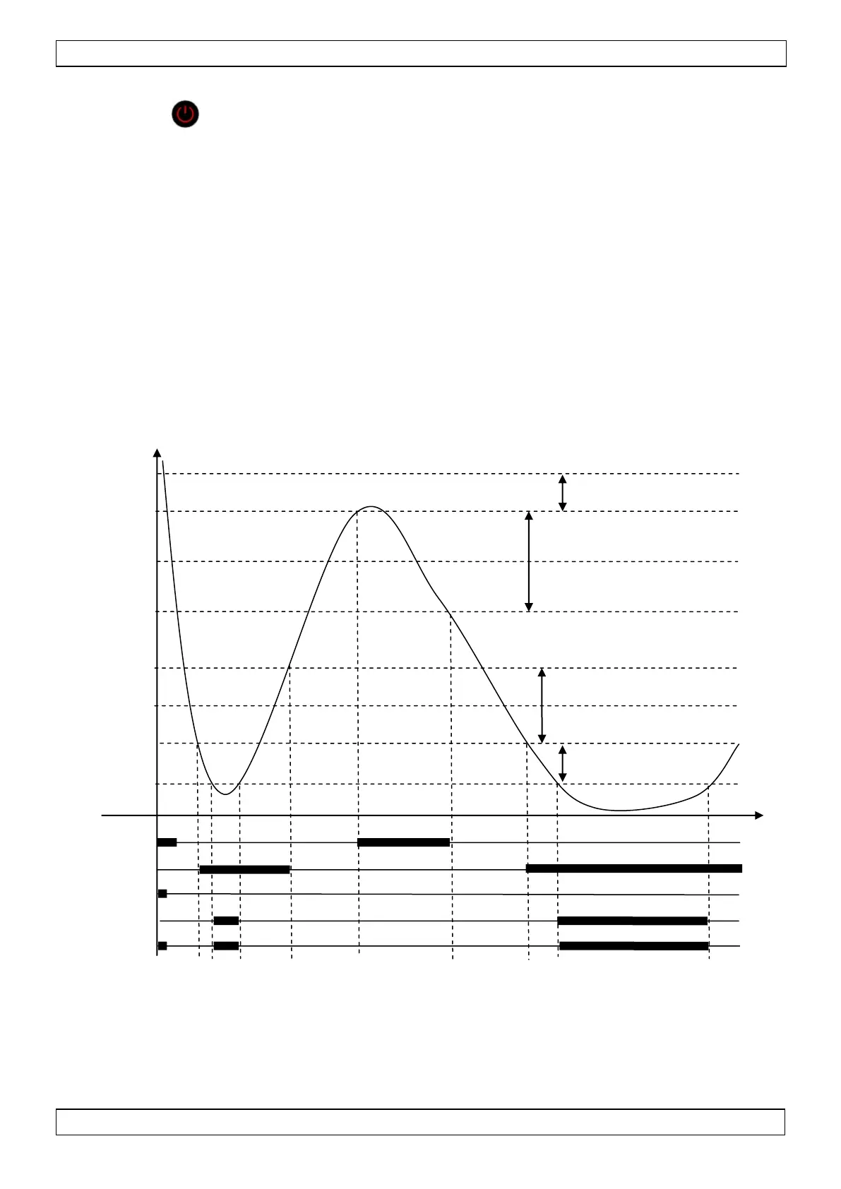
The adjustment method is shown in Figure 1:
Fig 1. Principle of controlling the relays by the control block in "cooling and heating given separately" - thick line
means switching the relay on
‘Heating set temperature’ is set by the user as parameter ‘u1’, in range of ‘d0’ - ‘d1-1’ (factory setting u1=2).
‘Heating activation temperature’ is calculated as ‘u1’ – value of heating hysteresis ‘d2’.
‘Heating off temperature’ is calculated as ‘u1’ + value of heating hysteresis ‘d2’.
Cooling activation temperature
Heating activation temperature
Temperature of overcooling alarm activation
Temperature of overheating alarm activation
 Loading...