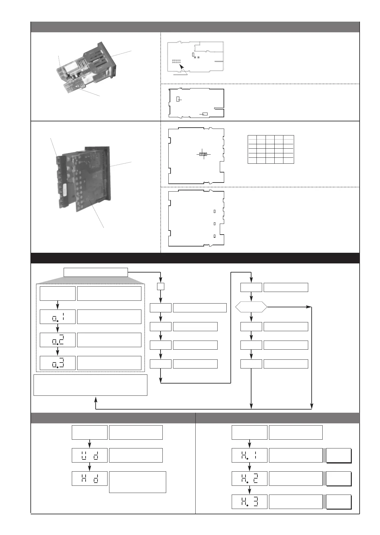
Device structure: identification of boards
-999 ... +999
scale points
• Information display
5 • PROGRAMMING and CONFIGURATION
(*) For deviation alarms the setpoint range is -999 ... 999
If the Inc, Dec, F keys are not pressed within 15 sec.,
the display returns to the P.V. value
I F
P.V.
Process variable
Alarm Setpoint Output 2 (*)
Alarm Setpoint Output 3 (*)
Password
C F
P A
PA = 99
P r
U.C.
Custom linearization
User calibration
YES
NO
Alarm Setpoint Output 1
LEVEL 1 DISPLAY
L n
Hysteresis parameters
Protection code
Information display
I F
Software version
Display CPU type
(potentiometer/strain-gauge)
and number of outputs available
b3= with 3 outputs
Information display
I n
Input settings
O u
Output settings
• Configuration parameters
C F
Hysteresis for set point 1
Hysteresis for set point 2
Hysteresis parameters
-999 ... +999
scale points
-999 ... +999
scale points
Hysteresis for set point 3
F
Pressed for
approx. 2 sec.
Keep the F key
pressed to browse
the menus.
Release the F key
to enter the
displayed menu.
Press the F key to
access the
parameters.
Keep the F key
pressed to exit any
menu at any time.
CPU BOARD + POWER
SUPPLY BOARD
OUTPUT BOARD
S1 = Status of Out 1 relay
S2 = Status of Out 2 relay
S3 = Status of Out 3 relay
A = Direct
B = Inverse
CPU BOARD + POWER
SUPPLY BOARD
OUTPUT BOARD
DISPLAY BOARD
S1 S2 S8 S9
1V OFF OFF OFF ON
5V ON OFF OFF OFF
10V OFF ON OFF OFF
15V OFF OFF ON OFF
24V OFF OFF OFF OFF
Sensor supply
POWER SUPPLY BOARD
24V
15V
10V
5V
1,23V
R20
S2
N.B. : you can keep the OUT1 relay energized at
power-up by inserting jumper S2 and removing
resistance R20.
3
81651C_MHW_40B48-96_0308_ENG
 Loading...