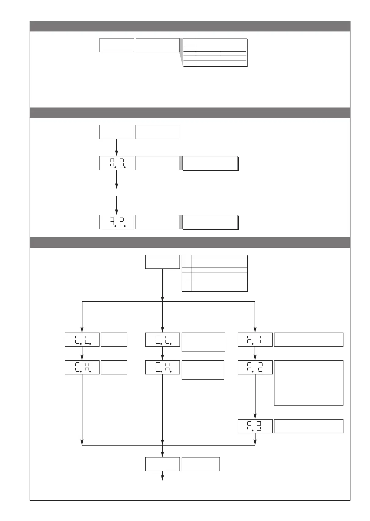
• Protection
Protection code
Value Displayed Modifiable
parameters parameters
0 o.1, o.2, o.3 o.1, o.2, o.3
1 o.1, o.2 o.1, o.2
2 o.1 o.1
3 o.1 none
+4 to disable In and Ou pages
+8 to disable Cf page
+16 to enable maintenance of reset memory at shutdown
+32 base configuration (the following parameters will not be displayed:
In: Ft, Fd, Of, L_L, H_L
Ou: On [forced to no. outputs present], rE)
P r
.......
• Custom Linearization
Custom Linearization of
main input
Step 0
(beginning of scale value)
Display limits
(-1999 to 9999 for 4 digit display)
Step 32
(full scale value)
Display limits
(-1999 to 9999 for 4 digit display)
L n
the n step value corresponds to input:
mV beginning scale + n *
∆mV
∆mV = (mV full scale - mV beginning scale) / 32
• User Calibration
U.C. CPU B function
1 analog retransmission
output
2 potentiometer
3 strain-gauge
positive polarization
4 strain-gauge
symmetrical polarization
U. C.
Minimum
calibration (*)
Maximum
calibration (*)
(*) Press keys ∆∇to
calibrate the analog
output
if U.C. = 1
Zero acquisition phase,
potentiometer with cursor
in minimum voltage
position
Maximum acquisition
phase, potentiometer
with cursor in maximum
voltage position
if U.C. = 2 if U.C. = 3, 4
Tare zero acquisition phase with strain-
gauge discharged (no weight or
pressure)
Acquisition phase for automatic definition
of sensitivity and full scale, load strain-
gauge with sample reference or
automatic activation of configured output
to check 6-lead sensor (only for version
SW 2.0x). 80% f.s. is set as default. The
value can be changed to set the value in
engineering units corresponding to the
sample used.
Zero recalculation phase, unload strain-
gauge by removing sample reference.
P.V.
Process variable
(LEVEL 1)
.......
enabled only if t.P = Linear Custom (only for version SW.2.0x)
Note: between the calibration phases some seconds could be requested to elaborate data.
5
81651C_MHW_40B48-96_0308_ENG
 Loading...