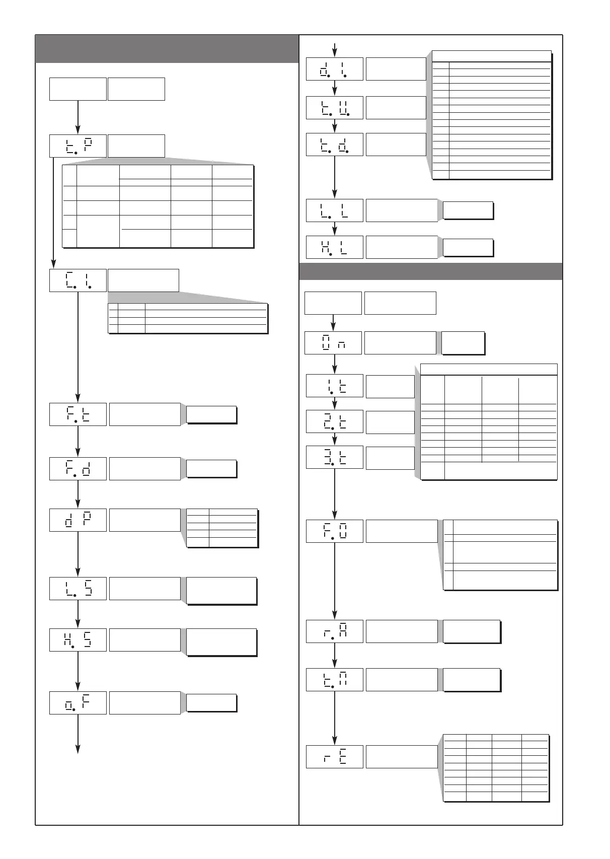
• Output parameters
0 None
1 Zero
2 Hold
3 Flash
4 Max. peak display
5 Min. peak display
6 Delta peak display
7 Peak memory reset
8 Zero + peak memory reset
9 Alarms reset
10 Peak + alarms reset
11 Zero + alarms reset
12 Peak + zero + alarms reset
13 Output status OUT1 / check CAL (*)
14 Output status OUT2 / check CAL (*)
15 Output status OUT3 / check CAL (*)
d. i. - t. u. - t. d.
Offset correction
of main input
Select function of
digital input
High limit for the alarms
set point
-999 to 999
scale points
L.S to H.S
Raise key function
(active only in
P.V.selection)
Low limit for the alarms
set point
L.S to H.S
Lower key function
(active only in
P.V.selection)
Value Direct Absolute Normal
(max.) Relative to Symmetrical
Inverse previous (window)
(min.)
0 Direct Absolute Normal
1 Inverse Absolute Normal
2 Direct Relativa Normal
3 Inverse Relativa Normal
4 Direct Absolute Symmetrical
5 Inverse Absolute Symmetrical
6 Direct Relativa Symmetrical
7 Inverse Relativa Symmetrical
+64 output for calibration of 6-lead sensor
(from version SW 2.0x)
Output settings
Number of outputs
Alarm type 1
0 to 3
1. t - 2. t - 3. t
Alarm type 2
Alarm type 3
+8 to disable on power-up until first alarm
+16 to memorize
+32 to filter with F.O. mode (output filter mode)
O u
min…max scale
of input selected in t.P
Maximum limit of main
input scale and analog
output
delay for F.O.
0 to 99 min or sec
Minimum output pulse 0 to 99 sec
Disabled by setting value 0
Displayed if associated with at least one output
Fault action (in case of
damaged sensor)
Er, br, Eb
Value Output 1 Output 2 Output 3
0 OFF OFF OFF
1 ON OFF OFF
2 OFF ON OFF
3 ON ON OFF
4 OFF OFF ON
5 ON OFF ON
6 OFF ON ON
7 ONONON
Output filter mode
0 not active: calculated status
is sent directly to relay
1 On delay (DON)
2 delay in activation of
output after output is
turned off (DBI)
3 Off delay (DOF)
4 Delay for activation
only at power-up (DPO)
+ 8 time base max. 99 min (default = 99 sec)
Decimal point position for
main input scale
dP Format
0 XXXX
1 XXX.X
2 XX.XX
3 X.XXX
Digital filter on
main input
Digital filter on process
variable display
0.0 to 20.0 sec
0.0 to 9.9
scale points
Minimum limit of main
input scale and analog
output
min…max scale of input
selected in t.P
• POTENTIOMETER / STRAIN-GAUGE
input parameters
Typ PROBE Signal 4 DIGIT 3 DIGIT
TYPE polarization + sign
Max Range Max Range
0 Potentiometer positive -1999/9999 -999/999
(ex. 0 / 1V)
1 Potentiometer positive Custom Custom
custom linear (ex. 0 / 1V) linear linear
2 Strain-gauge positive -1999/9999 -999/999
(ex. 0 / 10mV)
3 Symmetrical -1999/9999 -999/999
(ex. -10 / +10mV)
Input settings
Type of probe,
signal and scale of
main input
I n
Select sampling time
(resolution)
0 120ms > 13bit probe power supply control
1 120ms > 13bit; 8000 divs
2 60ms > 12bit; 4000 divs
3 30ms > 11bit; 2000 divs
+4 to disable filter (average of the last eight values sampled)
+8 disables Eb (sampling time is halved)
N.B.: maximum sampling frequency and minimum intercept time is
obtained with code 15 (15 msec, 11-bit resolution, filter off)
(*) for version SW 2.0x
4
81651C_MHW_40B48-96_0308_ENG
 Loading...