Read the following warnings before installing, connecting or using the device:
• follow instructions precisely when connecting the device.
• always use cables that are suitable for the voltage and current levels indicated in the technical specifications.
• the device has no ON/OFF switch: it switches on immediately when power is turned on. For safety reasons, devices permanently connected to the power
supply require a two-phase disconnecting switch with proper marking. Such switch must be located near the device and must be easily reachable by the
user. A single switch can control several units.
• if the device is connected to electrically NON-ISOLATED equipment (e.g. thermocouples), a grounding wire must be applied to assure that this
connection is not made directly through the machine structure.
• if the device is used in applications where there is risk of injury to persons and/or damage to machines or materials, it MUST be used with auxiliary alarm
units. You should be able to check the correct operation of such units during normal operation of the device.
• before using the device, the user must check that all device parameters are correctly set in order to avoid injury to persons and/or damage to property.
• the device must NOT be used in inflammable or explosive environments. It may be connected to units operating in such environments only by means of
suitable interfaces in conformity to local safety regulations.
• the device contains components that are sensitive to static electrical discharges. Therefore, take appropriate precautions when handling electronic circuit
boards in order to prevent permanent damage to these components.
Installation: installation category II, pollution level 2, double isolation
• power supply lines must be separated from device input and output lines; always check that the supply voltage matches the voltage indicated on the
device label.
• install the instrumentation separately from the relays and power switching devices
• do not install high-power remote switches, contactors, relays, thyristor power units (particularly if “phase angle” type), motors, etc... in the same cabinet.
• avoid dust, humidity, corrosive gases and heat sources.
• do not close the ventilation holes; working temperature must be in the range of 0...50°C.
If the device has faston terminals, they must be protected and isolated; if the device has screw terminals, wires should be attached at least in pairs.
• Power: supplied from a disconnecting switch with fuse for the device section; path of wires from switch to devices should be as straight as possible; the
same supply should not be used to power relays, contactors, solenoid valves, etc.; if the voltage waveform is strongly distorted by thyristor switching units
or by electric motors, it is recommended that an isolation transformer be used only for the devices, connecting the screen to ground; it is important for the
electrical system to have a good ground connection; voltage between neutral and ground must not exceed 1V and resistance must be less than 6Ohm; if
the supply voltage is highly variable, use a voltage stabilizer for the device; use line filters in the vicinity of high frequency generators or arc welders;
power supply lines must be separated from device input and output lines; always check that the supply voltage matches the voltage indicated on the
device label.
• Input and output connections: external connected circuits must have double insulation; to connect analog inputs (TC, RTD) you have to: physically
separate input wiring from power supply wiring, from output wiring, and from power connections; use twisted and screened cables, with screen connected
to ground at only one point; to connect adjustment and alarm outputs (contactors, solenoid valves, motors, fans, etc.), install RC groups (resistor and
capacitor in series) in parallel with inductive loads that work in AC (Note: all capacitors must conform to VDE standards (class x2) and support at least 220
VAC. Resistors must be at least 2W); fit a 1N4007 diode in parallel with the coil of inductive loads that operate in DC.
GEFRAN spa will not be held liable for any injury to persons and/or damage to property deriving from tampering, from any incorrect or
erroneous use, or from any use not conforming to the device specifications.
!
WARNING: this symbol indicates danger.
It is seen near the power supply circuit and near high-voltage relay contacts.
44
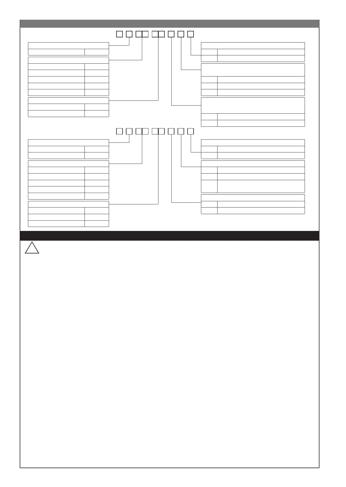
Triac, None T 0
Kindly contact GEFRAN for information on available codes.
100 to 240Vac1
Power supply
20 to 27Vac/dc0
Digital input / Retransmission output
(alternative to output 3)
None0
Digital input
Retransmission output 4...20mA on max 150Ω
1
2
N° Digits
44
40B
Output 3
(alternative to digital input / retransmission output)
None0
RelayR
5Vdc 05
Sensor power supply
1.2Vdc for potentiometer 01
24Vdc, 50mA (transmitter) 24
10Vdc, 120mA
15Vdc (transmitter)
10
15
• WARNINGS
ORDER CODE
Relay, Static D2 R D
Output 1, Output 2
Relay, Relay R R
48 4
100 to 240Vac/dc1
Power supply
11 to 27Vac/dc0
Digital input / Retransmission output
None0
Digital input
Digital input +
Retransmission output 4...20mA on max 150Ω
1
3
N° Digits
3 + sign 3
40B
Output 3
None0
RelayR
5Vdc 05
Sensor power supply
1.2Vdc for potentiometer 01
24Vdc, 50mA (transmitter) 24
10Vdc, 120mA
15Vdc (transmitter)
10
15
Relay, Static D2 R D
Output 1, Output 2
Relay, Relay R R
96
8
81651C_MHW_40B48-96_0308_ENG
 Loading...