1180961F_MSW_GTF/GTF-Xtra_07-2018_ENG
Input lter
Read state
ADVANCED SETTINGS
32
FT.A
R/W
CT input digital filter
0,0 ... 20,0 sec
2.0
94
I.taP
R
Peak ammeter input value during phase
softstart ramp
88
I.onf
R
CT filtered ammeter input value with
output activate
87
I.ta
R
Instantaneous current variable
104
ld.a
R
Current RMS of load
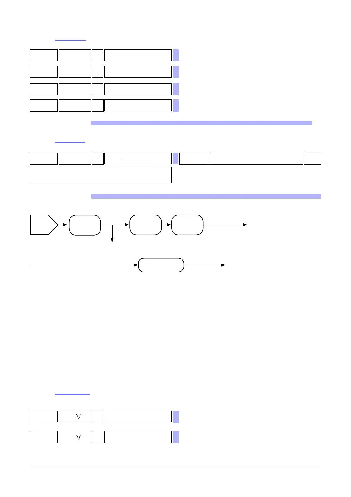
FUNCTIONAL DIAGRAM
(Instantaneous current)
Variable
I.tA
Variable
I.tAP
(Peak current)
CT auxiliary
input
Offset scale
limits
(o.tA)
Low pass
lter
(Ft.A)
(Current-output active)
variable
I.onF
Function (Ou.P)
(Load RMS current)
Variable
Ld.A
Management:
- HB Alarm
- Feedback I
- Irms limitation
- No Current Alarm
The line voltage interval for correct operation is 90…600VAC.
There are the following parameters:
I.tV instantaneous voltmeter value of line
I.tVF ltered voltmeter value
o.tV voltmeter input offset correction
Ft.V voltmeter input digital lter
RMS voltage values refer to the voltage between the terminal: 1/L1 and 3/L2.
It has a voltage presence check that shuts off the module in case of incorrect values.
A “STATUS 3” parameter contains information on the status of line voltage, including mains frequency identied 50/60Hz.
Scale limits
37
L.t
R Minimum scale limit of TV input
38
x.t
R Maximum scale limit of TV input
Sets a low pass lter on the CT auxiliary input, running the average of values read in the
specied time interval. If = 0 , excludes the average lter on sampled values.
Value
I.tA
SSR ON

 Loading...


