6
80961F_MSW_GTF/GTF-Xtra_07-2018_ENG
COMMUNICATIONS
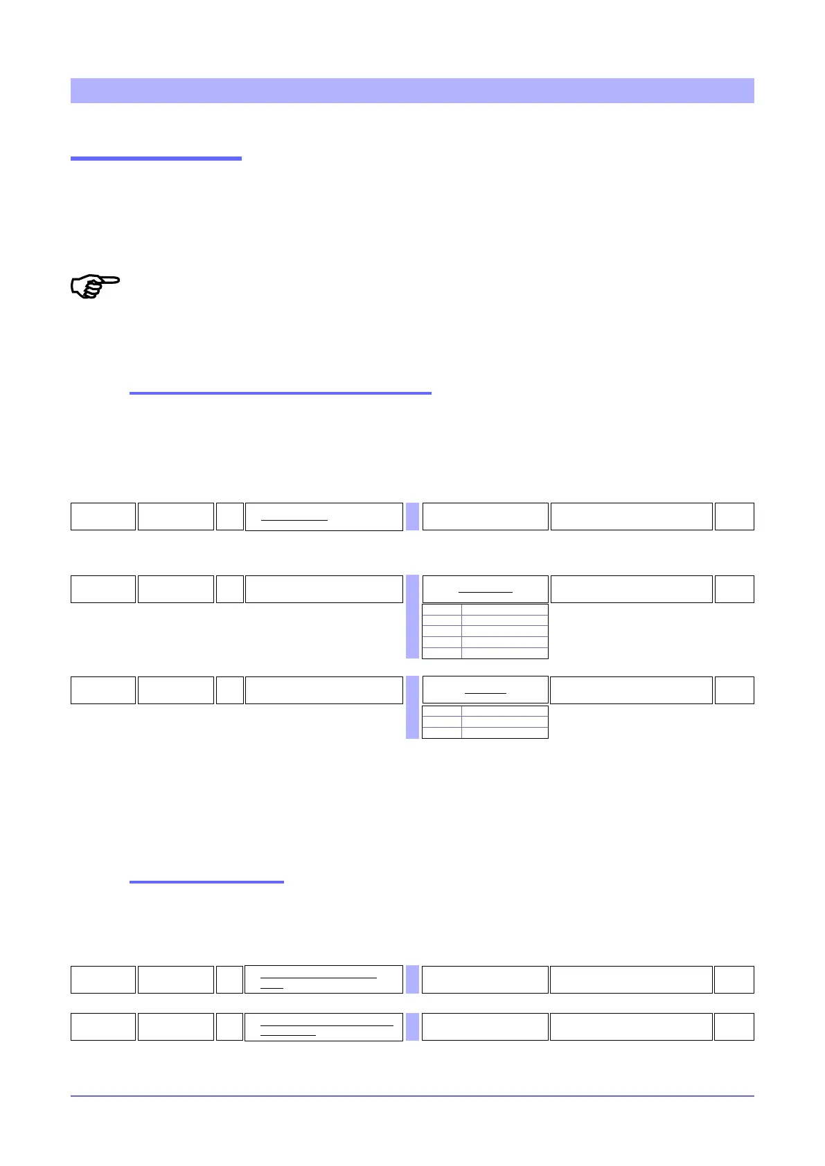
25
par
R/W
Select parity
0
Parity table
NOTES:
- ID code 0 is reserved to the Autobaud function
- The ID code is the image of the rotary switches acquired at power-on
24
baV
R/W
Select Baudrate
4
Baudrate table
0 1200 bit/s
1 2400 bit/s
2 4800 bit/s
3 9600 bit/s
4 19200 bit/s
23
(od
R Identification code 1 ... 99
1
0 No parity
1 Odd
2 Even
NOTE:
- Conguration via the TTL serial port is done with the following parameters:
Cod = 1
bAu = 4
PAr = 0
Communications
Each GTF has an optically isolated serial port TTL with standard Modbus for GTF 25-120A protocol via connector J2
type RJ10 (J5 for GTF 150-250A).
As an option, you may have an optically isolated RS485 serial port with standard Modbus protocol for GTF 25-120° via con-
nectors j3 and j4 type RJ10 (J6, J7 for GTF 150-250A).
The Cod parameter (read only) shows the value of the node address, settable from 00 to 99 with the 2 rotary switches acquired
power; the hexadecimal settings are reserved.
Changing the
bAu (select baud-rate) and/or PAr
(select parity) parameters may cause commu-
nication failure.
To set the bAu and PAr parameters, you have to run the Autobaud procedure described in the “Instruction and warnings”
manual. For TTL serial port, code Cod. is xed at 1.
Installation of the “MODBUS” serial network
A network typically has a Master that “manages” communication by means of “commands” and Slaves that interpret
these commands.
GTF are considered Slaves to the network master, which is usually a supervision terminal or a PLC.
They are positively identied by means of a node address (ID) set on the rotary switches (tens + ones).
Communication failure
If Modbus communication between the GTF and the Master node goes into Timeout, you can set an output power
value and transmit the alarm state to the relay output (RL parameter).
163
(.E.t
R/W
Timeout due to communication
failure
0 ... 99 sec Value 0 disables the function
0
164
(.E.P
R/W
Output power when communication
failure is active
0.0 ... 100.0 %
0.0

 Loading...


