10
80961F_MSW_GTF/GTF-Xtra_07-2018_ENG
33
L.tA
R Minimum scale limit of CT input
34
x.ta
R Maximum scale limit of CT input
CURRENT VALUE IN LOAD
The RMS current value is read in variable Ld.A of each zone.
Accuracy is better than 1% in start modes ZC, BF and HSC.
Accuracy is better than 3% in PA mode with conduction angle >90°, and better than 10% for lower conduction angles.
The circulating current in the load is acquired with a 0.2ms sampling time.
The following parameters are also available:
I.tA instantaneous ammeter value
I.onF current with active control
o.tA ammeter input offset correction
Ft.A ammeter input digital lter
If diagnostics detects a fault condition on the load, the yellow STATUS LED will enable..
The condition POWER FAULT in OR with HB alarm can be assigned to an alarm or identied in the state of a bit in
variable STATUS2
POWER_FAULT diagnostics is congurable with parameter hd.2, which can be partially enabled
SSR SHORT SSR module in short circuit
NO VOLTAGE power failure or interrupted fuse
NO CURRENT due to SSR module open or fuse or load interrupted
( NOTE: the No_Current alarm trips when the current value on the load is less than 4% of I_nominal of the product.
For example, for GTF-25A the alarm trips with load current below 1A).
For alarm HB (load partially interrupted), refer to the specic section of this manual.
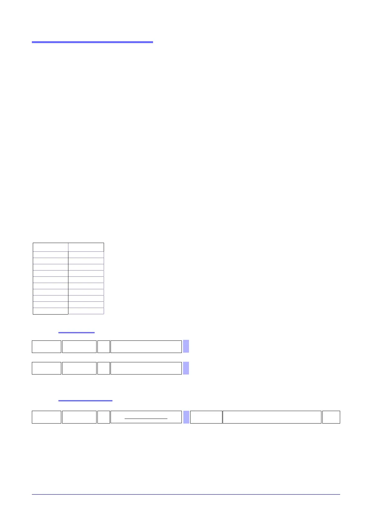
The default value of the maximum limit or ammeter full-scale depends on the model:
Scale limits
MODEL H.tA
25A 50,0
40A 80,0
50A 100,0
60A 120,0
75A 150,0
90A 180,0
120A 240,0
150A 300,0
200A 400,0
250A 500,0
Setting the offset
35
o.tA
R/W
Offset correction CT input
-99,9 ...99,9 A
0,0

 Loading...


