23(5$7,21
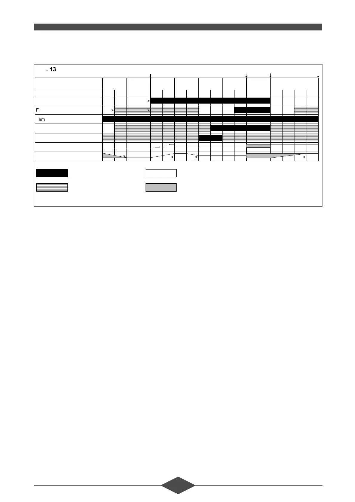
2SHUDWLQJGLDJUDP
3URJUDPPHVHTXHQFH
3KDVH6WDQGE\
The boiler is on standby awaiting a heat request.
A: Start-up instruction.
It is given by the RVA 47 regulator or the LGM it-
self with a d.h.w. request (display 6) or a heating
request (display 7).
3KDVH9HQWLODWRUVSHHGLQFUHDVHWLPH
This time ends as soon as the ventilator motor
speed reaches the programmed load for preven-
tilation.
3KDVH3UHYHQWLODWLRQWLPH
3KDVH7DSHULQJWLPH
This time ends as soon as the ignition load is rea-
ched.
3KDVH3UHLJQLWLRQWLPHV
Appearance of the ignition arc prior to opening
the gas valve, which occurs at the start of
phase 35.
3KDVH6DIHW\WLPHV
A flame signal should be present (ionization cur-
rent > 2.8 µA) before the safety time has elapsed.
If this does not occur, another ignition attempt is
made.
3KDVH%&%XUQHURSHUDWLRQ
Burner operation following a domestic hot water
request (display 6) or a heating request
(display 7).
3KDVH&'6KXWGRZQ
The switch from the operating position to the
Standby position is referred to as "shut-down"
and occurs when the heat request disappears.
The gas valve closes and the residues are eva-
cuated by post-ventilation.
3KDVH%ORFNLQJWLPH
Blocking time for test purpose (approx. 2 s).
3KDVH&ORVXUHWLPH
Required time to reach the programmed air flow
rate.
3KDVH3RVWYHQWLODWLRQWLPHV
The ventilator remains on during the post-ventila-
tion time.
3KDVH5HWXUQWRLQLWLDOSRVLWLRQ
Compulsory switch from the shut-down position
to standby. This phase is also used to bring the
safety control box to the standby position after ex-
ceptional events such as a RESET.
Signal required > Condition required to move on the next stage
Signal unacceptable range of possible speeds
ABCD
Display
90/123456./7. 8
Phase number
60 61 10 30 31 32 33 34 35 36 37 40 50 51 52 53
Heating demand
!
Flame signal
!
!
Temp. limiting safety device
Gas valve
Ignition
PWM
Fan speed
!
!! !
)LJ
 Loading...