,167$//$7,21
(/(&75,&$/&211(&7,21
- Electrical connection as well as any equipment
used to carry out this connection will conform to
the codes of practice in force and in particular to
standard NF C 15-100,
- the installation premises must be adapted to the
boiler’s level of protection (IP x 0D),
- mains voltage: 230 V - 50 Hz (single phase),
- earthing is compulsory,
- maximum electrical intensity absorbed by the
boiler without the accessories (heating pump -
domestic water pump, other RVA 46) is $
,
- the power supply will have to take into account all
the accessories connected to the different RVAs
bearing in mind that each of the regulators’ relays
handle a maximum intensity of 2 A each (see pa-
ragraph 1 - section II - TECHNICAL SPECIFICA-
TIONS in RVA 46 and RVA 47 technical
instructions),
- the power supply must feature a cut-out switch,
preferably bipolar, with a circuit-breaker or a fuse.
- Observe Live-Neutral polarity.
&RQQHFWLRQWRWKHQHWZRUN
The boiler is equipped with a 3 m power cable.
When connecting the socket, pay attention to Live-
Neutral polarity.
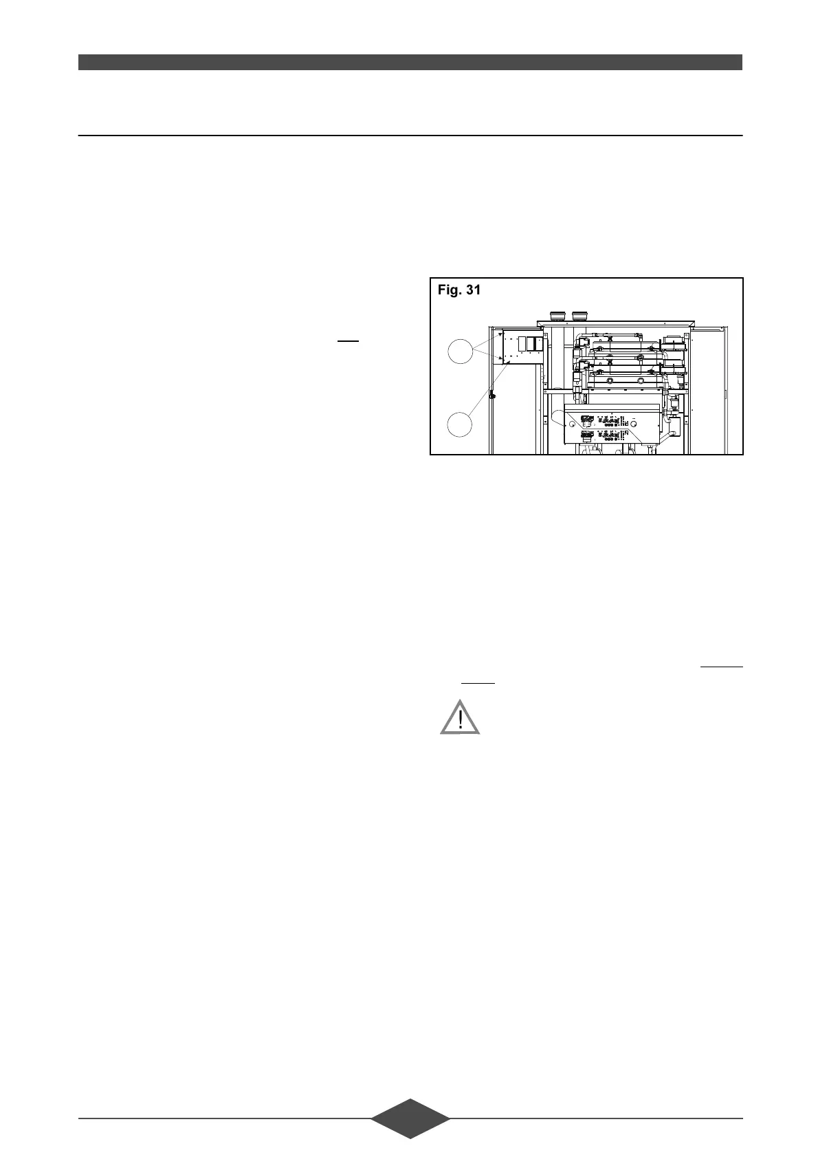
&RQQHFWLRQRISXPSVDQGVHQVRUV
The pumps and connectors are connected to the
terminals of regulator RVA 47 (see section V -
BASIC SETTING OF THE THR 10-100):
- Open the RVA box (item no. 24) once the two
screws have been removed (item no. 39),
- connect the following elements to the RVA 47:
• heating pump Q1,
• the two heating flow-return temperature sen-
sors QAD 21,
• outside sensor QAC 31,
For domestic hot water on a THR 10-100 C:
• domestic hot water sensor QAZ 21,
• domestic hot water load pump Q3,
For domestic hot water on a THR 10-100 CS:
• domestic hot water sensor QAZ 21 on the
LGM.
)RUWKHFRQQHFWLRQRIVHQVRUVFRQQHFW
WKHFRPPRQWRWKHSURYLGHGWHUPLQDOV
24
39
$=:
)LJ
!
 Loading...